
Water bottle for a dispenser

a dispenser and water bottle technology, applied in the field of containers, can solve the problems of pet bottles, not being useful in a returnable mode, not being able to survive repeated washing of pet bottles, etc., and achieve the effects of reducing the spacing between bottles, reducing weight and ease of handling, and reducing the pressure poin

Inactive Publication Date: 2006-05-30
ODAY JR WILLIAM R
View PDF42 Cites 55 Cited by
  • Summary
  • Abstract
  • Description
  • Claims
  • Application Information

AI Technical Summary

Benefits of technology

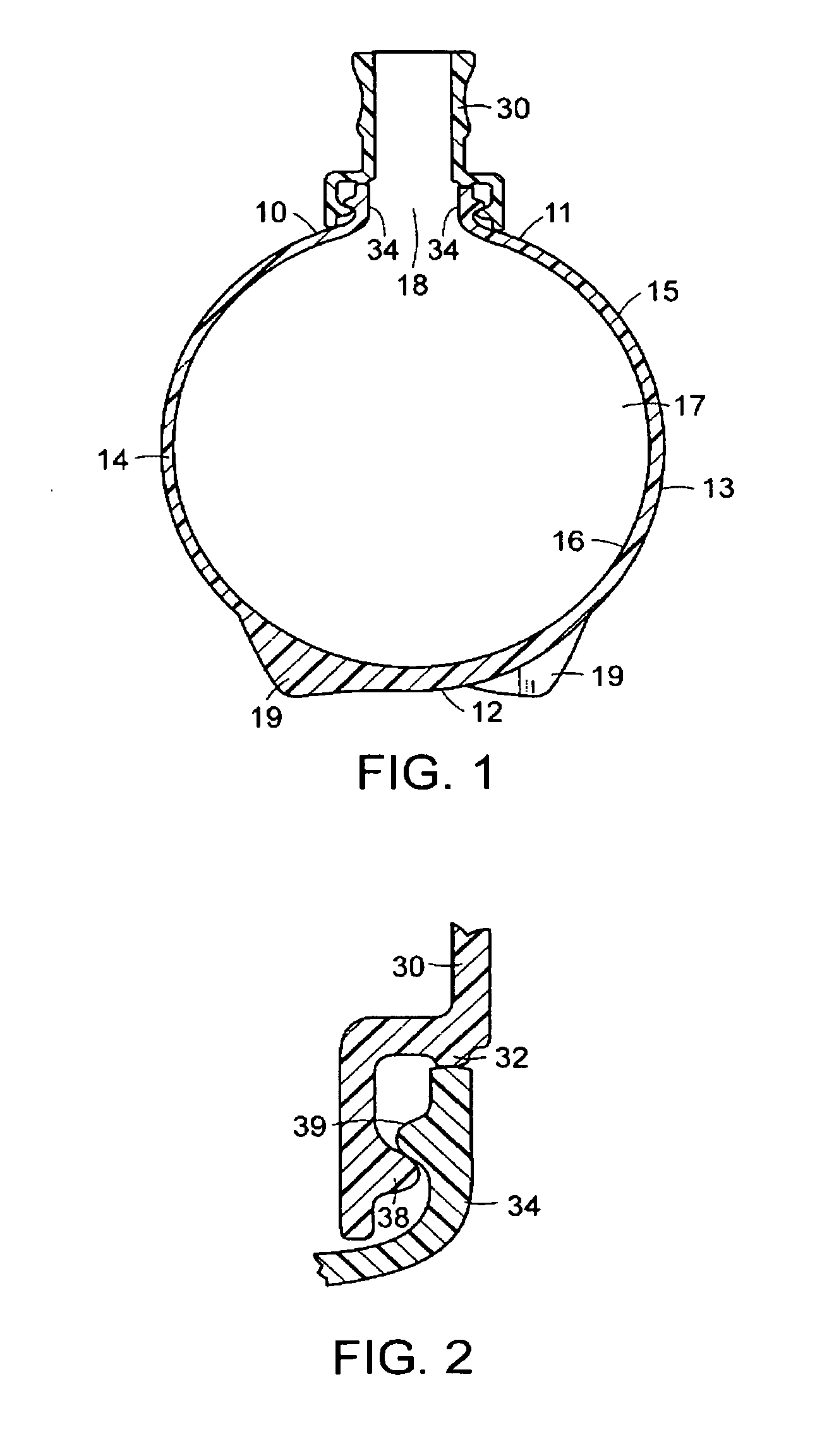
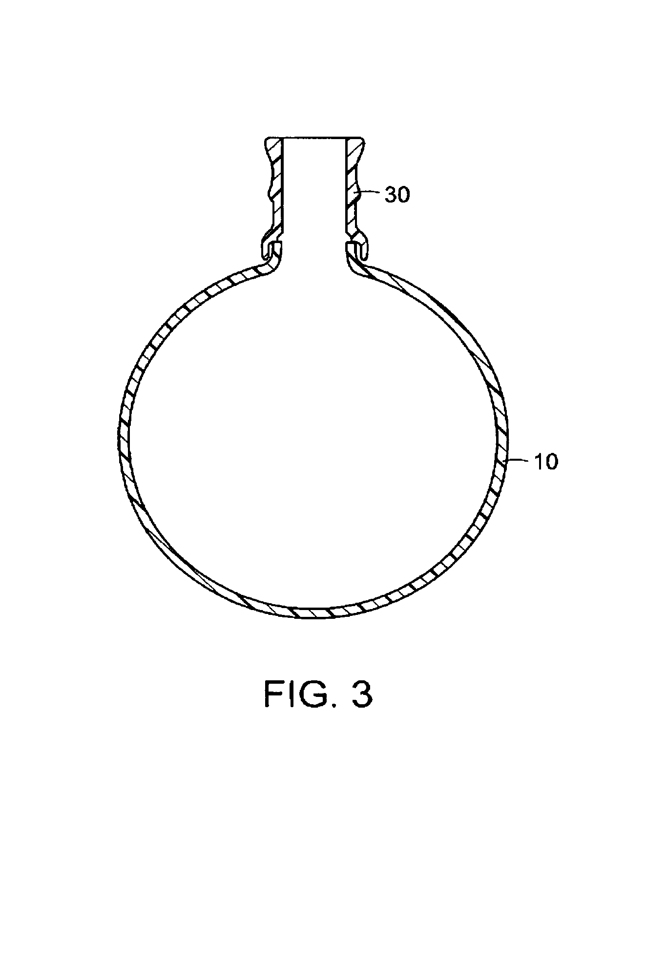
[0011]The invention begins with a spherical 5 gallon (approximately 19 liters) container which will have a resin / liter weight of only about 320 grams, or 17 grams / liter. The shape change results in a nearly 30% savings in resin weight over a traditional carboy shape.
[0012]A spherical shape has the lowest surface area per volume contained of any geometrical shape. A sphere will have a 14% geometric advantage over a 10.6 inch diameter cylinder in terms of surface area and of weight at the same wall thickness. The advantage rises to 20% when the carboy has a 9 inch diameter. Surface area times thickness is the determinant of resin volume used to manufacture the bottle. With regard to a vacuum, a sphere is the natural design choice to resist external pressures as evidenced by the fact that deep-water submersibles are all spherical in shape. The spherical shaped water bottle therefore allows the use of less resin to make a container of any given volume of contents, e.g., 3 gallons, 4 gallons, 5 gallons, etc.
[0014]A sphere full of water will immediately, upon being subjected to an external force at one point (impact or force), generate an internal pressure increase which will counteract the force and prevent collapse of the container. This is also true of top load, which is the force that a bottle is subjected to when it is stacked in layers for storage or transportation such as on a pallet. It is almost impossible to collapse a full spherical bottle because this reactive force, contained by the resulting tension in the container walls, will not allow the bottle to collapse. In contrast, a cylinder, when subjected to top load, wants to become spherical, which it can only do by bending the side walls which under unstable conditions can buckle the side walls. When this happens, the walls will not be under tension (a stable condition) until the walls approach a spherical shape. Therefore, a sphere can have a thinner wall than a cylinder and have the same or better mechanical properties.
[0015]There is also a natural improvement in stability of the container when it is a sphere rather than a cylinder. A spherical container will have a lower center of gravity. A sphere is always balanced when being rotated, such as when a person is putting it onto the dispenser. In contrast, a cylinder's weight exerts a varying force on the person's arms as it is rotated and can cause loss of balance.
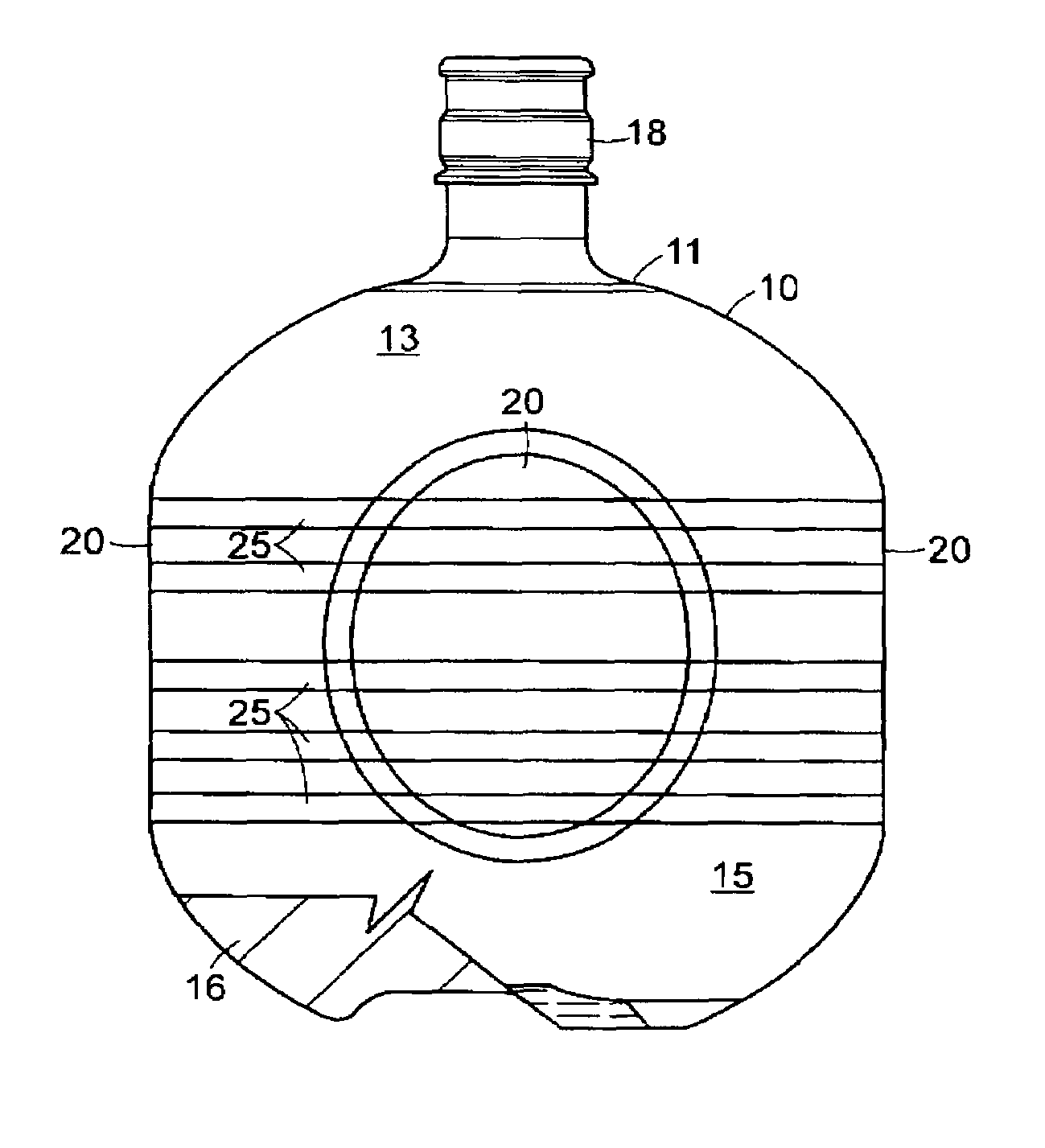
[0018]Another way to address the spherical shape packaging problem is by forming flat spots on the equator of the sphere, thereby reducing spacing between bottles without substantially penalizing the spherical-oriented design in terms of volume contained. The use of flat spots allows close packing of the bottles for maximum packing density. The sphere only has to be made slightly larger in diameter to return the capacity to its original value after making flat spots.
[0019]Another advantage of a spherical bottle with flat spots is that a guiding surface is created which will allow the bottle to maintain its orientation relative to filling, labeling, capping, palletizing, and other equipment which might benefit from the ability to maintain the orientation of the bottle. Furthermore, during shipment the bottles will not tend to rotate and scuff against each other. The flat spots will provide a larger contact surface and, therefore, a lower pressure point caused by inter-bottle contact and vibration during transportation. Since standard 5 gallon containers filled with water are quite heavy, i.e., 43 pounds, in the present invention, the preferred bottle capacity is between 3 and 4 gallons for reduced weight and ease of handling. The 4 gallon container with flat spots will have a flat spot to flat spot, side-to-side dimension which is the same as diameter of a traditional 5 gallon, cylindrical carboy, i.e., 27 centimeters or approximately 10.6 inches. Another advantage of a container with flat spots is that labels can be placed on the flat areas.

Problems solved by technology

The marketing system for the bottles filled with water includes delivery and pick-up services which require considerable investment and is considered to be quite labor intensive.
PET bottles, however, are not useful in a returnable mode because PET has limitations regarding temperature above 70 degrees C. / 160 degrees F. This does not allow the bottle made of PET to survive repeated washing at normal elevated temperatures required for sanitation purposes.
Furthermore, such bottles tend to be quickly degraded by the rigors of outdoor storage and exposure to high temperatures of delivery trucks in the hot sunlight.
Also, the sale of water in one-way 5 gallon PET bottles has been limited due to the weight of resin used in making the container and the consequent cost of the bottle when it is used once and then recycled.
However, early designs of one-way PET carboys did not achieve this improvement and required 450 grams for a 5 gallon carboy, i.e., 24 grams / liter, mainly because of vacuum problems associated with dispenser-mounted bottles.
Lightweight PET carboys can collapse under the vacuum created by water as it is dispensed from the bottle and can fall off the dispenser spilling water out of the bottle onto the floor.
However, this requires the carboy to be taller for the same volume and increases the amount of resin used.

Method used


Image

  • Water bottle for a dispenser
  • Water bottle for a dispenser
  • Water bottle for a dispenser

Examples


third embodiment

[0045]In one embodiment of the invention the wall 13 has a spherical shape. See FIG. 1. In another embodiment of the invention the wall 13 has an oval shape. See FIG. 5. In another embodiment of the invention, the wall 13 has a plurality of flat areas 20 about its equator 14, said flat areas being equispaced about said equator 14. See FIG. 10. In another embodiment of the invention, the water bottle's capacity is increased by adding a short cylindrical section to the middle of the container, i.e., expanding the equator. This will allow more volume to be contained in a bottle with a smaller diameter. The above embodiment may be combined with the flat area embodiment for a third embodiment, wherein a waisted bottle with a plurality of flat equator areas may be provided. See FIG. 12.

[0046]The uniqueness of these embodiments is the combination of a spherical shape which has certain mechanical characteristics and the flat areas that provide desirable bottle spacing characteristics plus s...

first embodiment

[0063]In another embodiment of the invention a bottle is provided with four flat sides. Although this embodiment does not palletize as well as the hexsphere or the twelve-sided bottle, this version satisfies the filling conveyor width and bottle separation requirements. This embodiment has more spherical surface that the hexsphere and the diameter of the sphere before lopping off the panel areas can be smaller because fewer areas are made flat. The horizontal ribs that are added to the first embodiment are required strengthening elements for this embodiment as well. A disadvantage of the four sided embodiment is that the bottles must be arranged in a cubical arrangement on pallets instead of in a hexagonal arrangement which is more efficient in terms of packing density.

[0064]The bottle's capacity may be increased by adding a short cylindrical section 26 the middle of the container, i.e., expanding the equator by increasing its waist. This will allow more volume to be contained in a ...


PUM


Abstract

A plastic, blow-molded, disposable water bottle adapted for use with a dispenser, said bottle having a basically spherical or elliptical shape, a footed base portion, and a unique neck geometry.

Description

CROSS-REFERENCE DATA TO RELATED APPLICATIONS[0001]Applicant claims the priority benefits of U.S. Provisional Patent Application 60 / 515,067, filed Oct. 28, 2003; U.S. Provisional Patent Application 60 / 542,167, filed Feb. 5, 2004; and U.S. Provisional Patent Application 60 / 554,037, filed Mar. 16, 2004. This application is a continuation-in-part of U.S. Design patent application No. 29 / 209,236, filed Jul. 12, 2004, pending.BACKGROUND OF THE INVENTION[0002]This invention relates to containers, and in particular, to a water bottle adapted for use with a dispenser.[0003]Presently, water is sold for home, office or retail use in large bottles. Bottles of this type usually include a generally cylindrical body, a generally frustoconical top breast at the upper end of the body, and a tubular filling and dispensing neck projecting upwardly from the central portion of the breast. Bottles of this type usually are inverted and installed on a gravity-type dispenser. In order to enable the bottle t...

Claims


Application Information

Patent Timeline
Patent Type & Authority Patents(United States)
IPC IPC(8): B65D23/00
CPCB65D1/0223B65D1/0276B65D1/023B65D2501/0081
Inventor O'DAY, JR., WILLIAM R.
Owner ODAY JR WILLIAM R
Learn More