Interlockable partition panel and method of fabrication the same

A technology of dividing plates and dividing walls, used in building structures, building components, walls, etc.

Inactive Publication Date: 2019-05-14
CASTLEBRITE PTE LTD
4 Cites 3 Cited by

AI-Extracted Technical Summary

Problems solved by technology

Other issues include assembly using wires or the like, and in some ...

Method used

[0045] According to a preferred embodiment of the present invention, said partition panels form a partition wall that is suitable for interior walls of all building types, such as residential, commercial and industrial, with high-quality surface treatment and high sound and thermal insulation performance, which depends on end user preferences and requirements.
[0046] The installation of lightweight si...

Abstract

An interlockable partition panel and a method of fabrication the same are provided. The interlockable partition panel is substantially rectangular and suitable for office plan or residential rooms, and includes a plurality of panels having protruded edge formed along the edges of the longer side of the panel defining a channel therebetween adapted to house cables and the like therein, and having aplurality of gap holes spaced apart along the lateral edge of the panel; a first locking mechanism mounted at the gap holes; and a second locking mechanism inserted into the first locking mechanism so that the panels are alignedly mounted and securedly formed as a partition wall.

Application Domain

Walls

Technology Topic

EngineeringSurface plate +1

Image

  • Interlockable partition panel and method of fabrication the same
  • Interlockable partition panel and method of fabrication the same
  • Interlockable partition panel and method of fabrication the same

Examples

  • Experimental program(1)

Example Embodiment

[0030] Reference When describing the preferred embodiments of the present invention in detail, examples thereof are shown in the accompanying drawings. The preferred embodiments of the present invention are not intended to limit these embodiments of the present invention in the broadest aspect. On the contrary, the present invention is intended to cover alternatives, modifications and equivalents that may be included within the spirit and scope of the invention as defined by the appended claims.
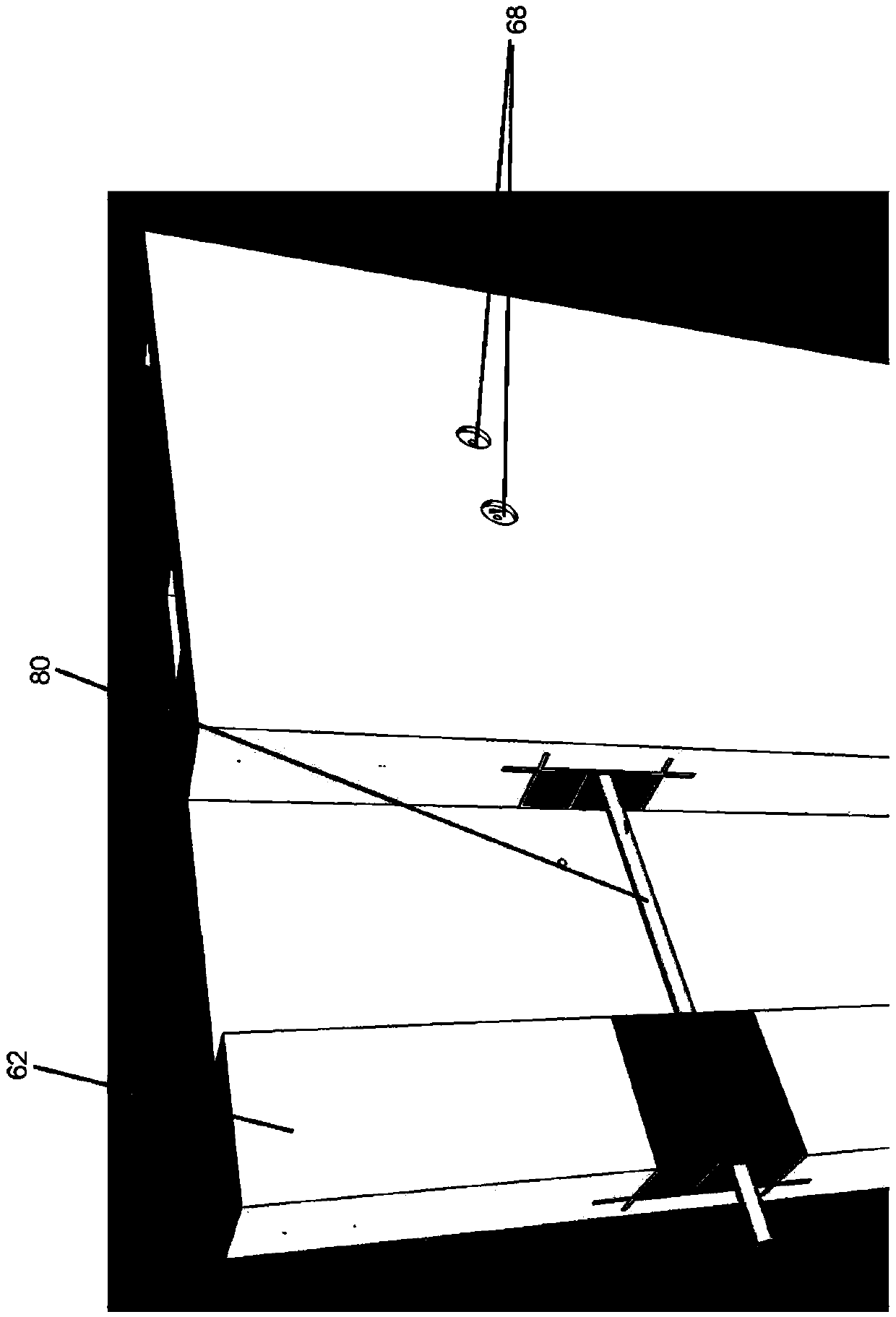
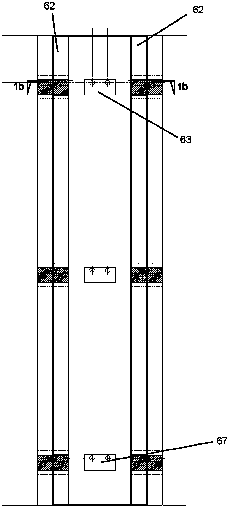
[0031] See figure 1 and figure 2 , Which shows an interlockable partition plate 600 according to an embodiment of the present invention. The partition plate 600 is rigid and has a generally rectangular shape. The longitudinal edge of the partition plate 600 is provided with a protruding edge 62, and a plurality of spacing holes 63, 65, 67 are formed on the protruding edge 62 at intervals for fixing an interlocking mechanism. A recess 69 is formed between the plurality of protruding edges. A plurality of screw holes 68 are formed on the surface of the partition plate 600 aligned with the plurality of spacing holes 63, 65, 67. The plurality of spacing holes 63, 65, 67 are used by an interlocking mechanism when two partition plates or more than two partition plates 600 are arranged vertically adjacent to each other, so that these partition plates 600 Lock together.
[0032] In a preferred embodiment, the shape and size of the spacer hole are not limited, and it can be round, cylindrical, square, rectangular, etc., and the size of the spacer hole allows a metal rod or metal The strip passes through as a locking mechanism. An example of the locking mechanism 80 is an aluminum extrusion bracket or the like.
[0033] The partition board 600 is made of concrete mixture or related materials. The present invention provides an economical and light-weight partition board system, which is rigid, strong, durable, environmentally friendly, and versatile, and most importantly, the partition board 600 is easy to install and disassemble, and does not require special use. Tools or devices.
[0034] See Figure 5 , Which shows a top view of the partition plate of the present invention. As shown in the figure, the panel and the plurality of panels 600 are arranged vertically to form a partition system, and two protruding edges 62 are shown on the sides thereof. A plurality of screws 71 are used to mount the panels to each other and to fix one edge of the panels that are installed oppositely. Set all the panels in place to form a strong partition wall.
[0035] Of the invention Image 6 and Figure 7 The front and side views of the interlocking mechanism are shown. As shown in the figure, the two hollow squares 76, 78 are specially designed to install conduits or the like with different requirements. This structure provides the installation flexibility of the duct or the like, and the partition plate can still be installed on a wall to effectively achieve the hiding effect.
[0036] figure 1 The perspective view shows an interlocking mechanism inserted into a second interlocking mechanism to ensure that the panel is fixed in place. As shown in the figure, at least two partition plates 600 are vertically arranged side by side, and the first locking mechanism is inserted into the spacing hole of the panel first, and then inserted into the second interlocking mechanism 80 . This installs the panel.
[0037] figure 1 The perspective view of shows a complete wall locked by the locking mechanism 80 of the present invention. The lockable mechanism 80 is applied to allow the end user's voice needs to adjust the width of the wall. This application can effectively hide the protruding columns in the retractable space to create a comfortable room or a space area in a specific area in the regional space. Filling is necessary, and the material of this filling is flexible in order to meet the requirements of end users, and we also consider the application of various materials to have different effects on acoustic performance. The partition plate is stable and high in strength.
[0038] figure 2 It shows a connection mechanism applied to a wall that allows a variety of width changes to meet the sound needs of end users. This application can effectively hide the protruding columns in the retractable space to create a comfortable room or a space area in a specific area in the regional space. Filling is necessary, and the material of this filling is flexible in order to meet the requirements of end users, and we also consider the application of various materials to have different effects on acoustic performance.
[0039] According to the present invention, the partition wall composed of multiple partition panels is manufactured as follows:
[0040] More than one partition plate 600 is vertically arranged, and an aluminum extrusion bracket as the first locking mechanism is fixed at the gap hole. One or more fixing rods serving as the second locking mechanism are inserted into the first locking mechanism, so that a plurality of partition plates 600 are fixed together. In this preferred embodiment, only two panels are shown for illustrative purposes.
[0041] From the side of the wall:
[0042] According to the preferred embodiment, the panel 600 is provided with two edges 62, such as figure 1 As shown, it protrudes from the back edge of the panel 600, and a channel 69 is formed between the two protruding edges 62. The two panels 600 are fixed by a first interlocking mechanism, such as a bracket, to form a partition wall. The plurality of panels 600 must be aligned with the first interlocking mechanism so that the second interlocking mechanism (such as a rod) can be inserted, so that two partition plates 600 are provided to form a wall.
[0043] The wall:
[0044] The first interlocking mechanism is aligned with the two sides of the wall, and a channel 66 is provided for the insertion of the second interlocking mechanism to fix all panels in place. The partition 600 of the second group is arranged so that one of the protruding edges 62 of the first group is located in the channel 66 of the second group. The second locking mechanism is used to fix all panels in place to form a wall.
[0045] According to a preferred embodiment of the present invention, a partition wall formed by the partition panel is an internal wall suitable for all types of buildings, such as residential, commercial and industrial, with high-quality surface treatment and high sound and heat insulation performance. It depends on the end user's preferences and requirements.
[0046] The installation of lightweight siding does not require skilled workers; therefore, this not only reduces labor costs, but also improves the efficiency of the construction process. In addition, there is no need for wet trade or plastering during the installation process, which saves time and costs from material requirements; for example, using polyurethane fillers, which can be easily passed through solvents Remove, therefore, these panels can be reused to a large extent.
[0047] Due to the application of the first and second interlocking mechanisms (bracket and metal rod), only very small damage may occur during the process of disassembling the partition wall of the present invention, which means that this panel is reusable, To create an environmental perspective.
[0048] The embodiments shown and described above are all exemplary. All details, parts, components or steps described and shown are not claimed to be invented herein. Although many features and advantages of the present invention have been described in the drawings and specific embodiments, these descriptions are only illustrative and can be changed in details, especially in terms of shape, size and arrangement within components . The principle of the present invention is expressed in the broad meaning of the terms of the appended claims.

PUM

no PUM

Description & Claims & Application Information

We can also present the details of the Description, Claims and Application information to help users get a comprehensive understanding of the technical details of the patent, such as background art, summary of invention, brief description of drawings, description of embodiments, and other original content. On the other hand, users can also determine the specific scope of protection of the technology through the list of claims; as well as understand the changes in the life cycle of the technology with the presentation of the patent timeline. Login to view more.
Why Eureka
Try Eureka