
Beam detection method and device

A detection method and beam technology, applied in the field of communication, can solve problems such as lack of good detection downlink beam communication quality

Active Publication Date: 2019-05-14
DATANG MOBILE COMM EQUIP CO LTD
View PDF8 Cites 10 Cited by
  • Summary
  • Abstract
  • Description
  • Claims
  • Application Information

AI Technical Summary

Problems solved by technology

[0007] The present application provides a beam detection method and device, which are used to solve the problem of lack of good communication quality for detecting downlink beams in the prior art

Method used


Image

  • Beam detection method and device
  • Beam detection method and device
  • Beam detection method and device

Examples


Embodiment Construction

[0063] In order to make the purpose, technical solution and advantages of the application clearer, the application will be further described in detail below in conjunction with the accompanying drawings.

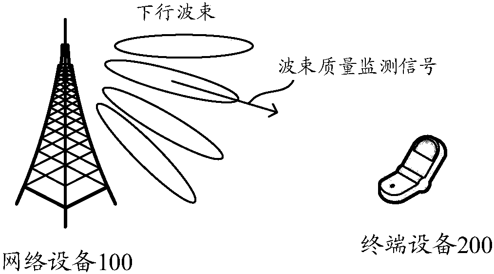
[0064] The present application provides a beam detection method and device, which are used to solve the problem of lack of good communication quality for detecting downlink beams in the prior art. Wherein, the method and the device are based on the same inventive concept, and since the principles of the method and the device to solve problems are similar, the implementation of the method, the device and the method can be referred to each other, and the repetition will not be repeated.

[0065] A plurality referred to in this application refers to two or more than two. In addition, in the description of the present application, words such as "first" and "second" are only used for the purpose of distinguishing descriptions, and cannot be understood as indicating or implying rela...


PUM


Abstract

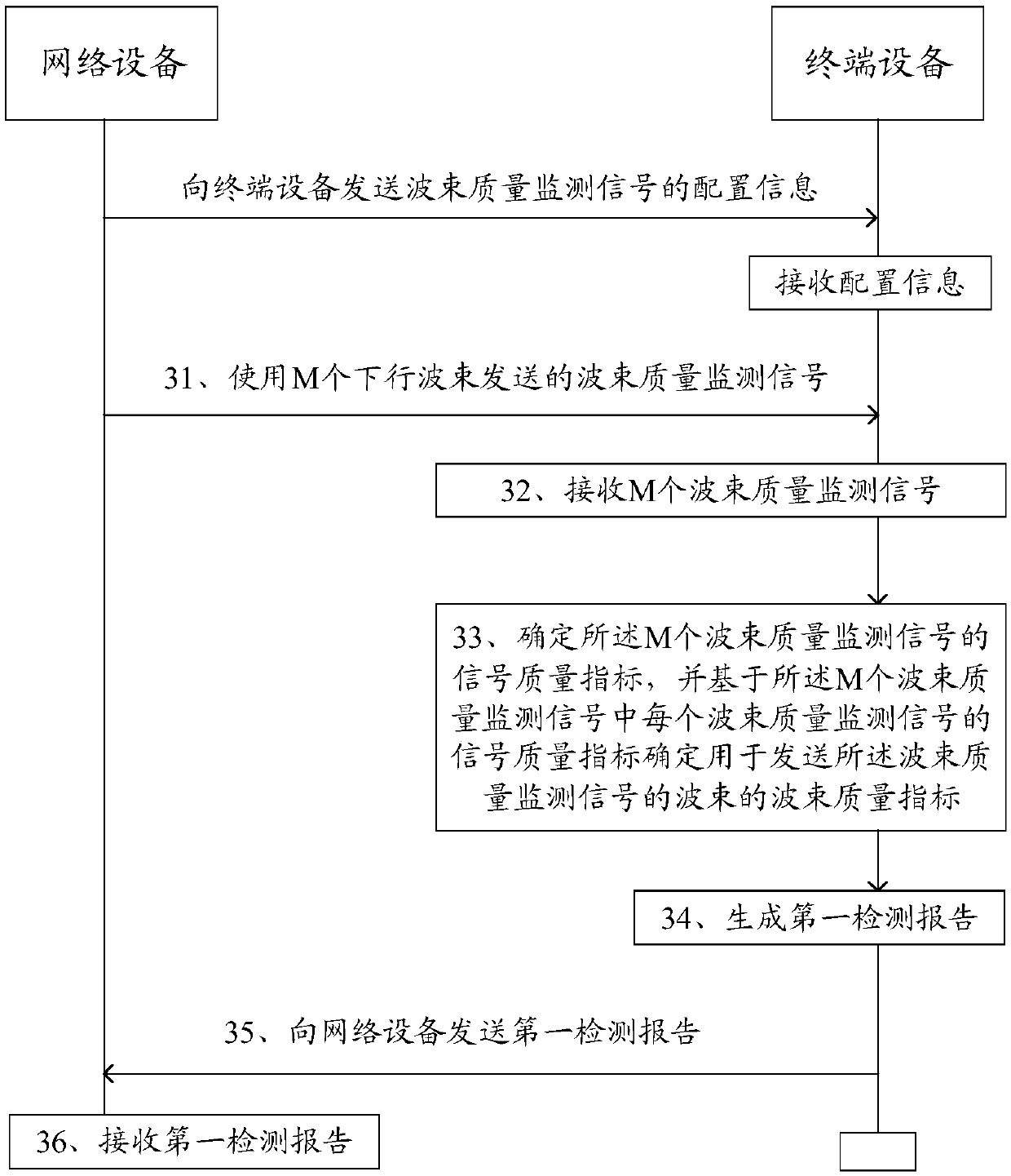
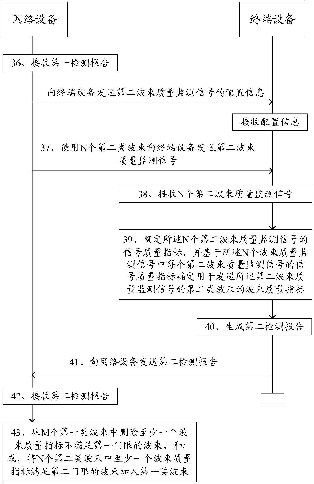
The invention discloses a beam detection method and a beam detection device, which are used for solving the problem of lack of good communication quality for detecting downlink beams in the prior art.The beam detection method comprises the following steps: the terminal equipment receives a beam quality monitoring signal sent by the network equipment by using M beams; Determining signal quality indexes of the M beam quality monitoring signals, and determining a beam quality index of a beam for sending the beam quality monitoring signal based on the signal quality index of each beam quality monitoring signal in the M beam quality monitoring signals; Generating a first detection report, The method comprises the following steps: indicating information of beams of which at least one beam quality index does not meet a first threshold in M beams, wherein the at least one beam quality index does not meet at least one of the beam quality index of the beam with the first threshold, the indication information of the beam with the at least one beam quality index meeting the second threshold and the beam quality index of the beam with the at least one beam quality index meeting the second threshold; And sending the first detection report to the network device.

Description

technical field [0001] The present invention relates to the technical field of communications, in particular to a beam detection method and device. Background technique [0002] Beamforming technology is a multi-antenna transmission technology. By adjusting the weighting factor on each antenna unit, the width and direction of the beam can be flexibly adjusted to transmit wireless signals in a specific direction. [0003] The network device can perform beamforming on the downlink control channel (physical downlink control channel, PDCCH) to obtain the space diversity gain of the multi-antenna array. A possible beamforming method for the PDCCH is: the time available for PDCCH transmission / Frequency resources are divided into multiple components, and each component is called a control resource set (control resource set, CORESET). The network device can transmit downlink control information (downlink control information, DCI) on any CORESET through the downlink beam. ) of the ...

Claims


Application Information

Patent Timeline
Patent Type & Authority Applications(China)
IPC IPC(8): H04B17/10H04L12/26H04W24/02
CPCH04B17/10H04B7/0617H04B7/0632H04B7/063H04W24/10H04B17/15H04B7/0408H04B17/309H04W24/02H04W16/28H04W92/10H04W92/02H04W72/046H04W88/02H04W84/02H04W88/08
Inventor 黄秋萍陈润华高秋彬
Owner DATANG MOBILE COMM EQUIP CO LTD
Learn More