Insulation structure of gas supply pipeline of Hall thruster

A Hall thruster and gas supply pipeline technology, applied in thrust reversers, machines/engines, and plasma utilization, etc., can solve the problems of limited connection between gas supply pipelines and storage and supply systems, and prone to insulation failure. Low manufacturing cost, simple structure, and the effect of preventing insulation failure

Active Publication Date: 2019-05-21
HARBIN INST OF TECH
View PDF4 Cites 4 Cited by
  • Summary
  • Abstract
  • Description
  • Claims
  • Application Information

AI Technical Summary

Problems solved by technology

[0003] The present invention aims to solve the problem that the connection between the gas supply pipeline and the storage and supply system is limited and the insulation fail

Method used


Image

  • Insulation structure of gas supply pipeline of Hall thruster
  • Insulation structure of gas supply pipeline of Hall thruster

Examples


specific Embodiment approach 1

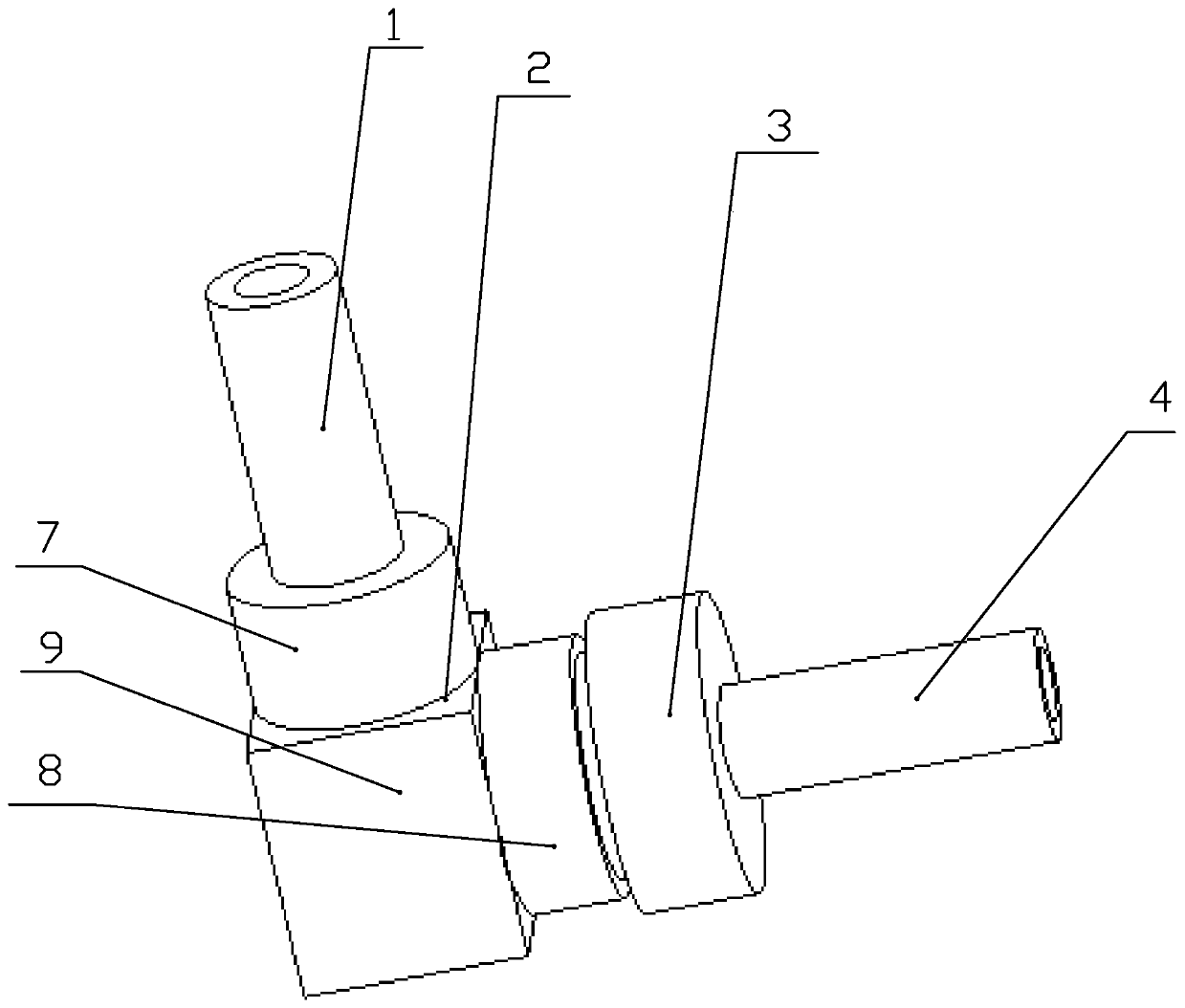
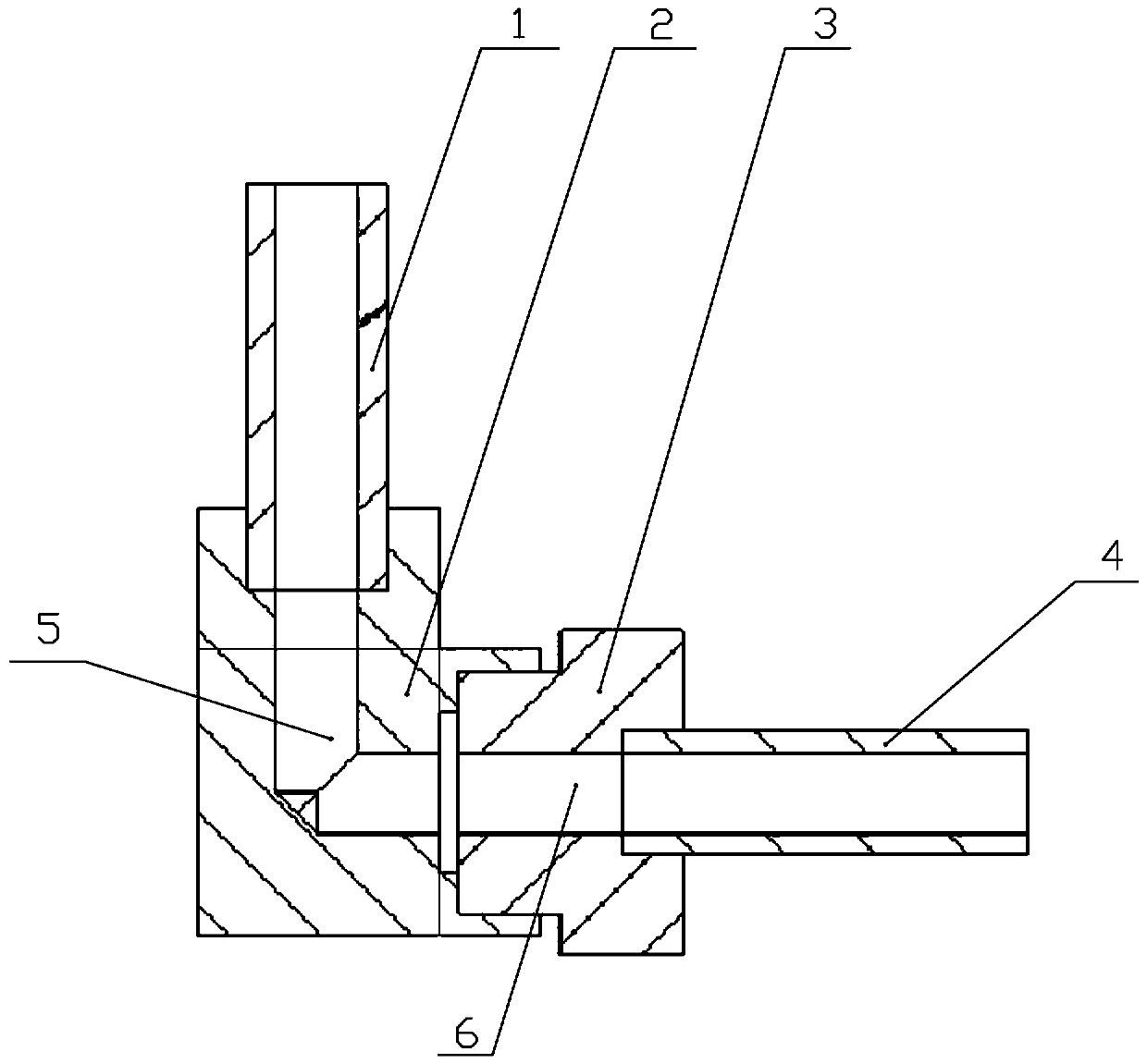
[0017] Specific implementation mode one: combine figure 1 , 2 Describe this embodiment, an insulation structure of a Hall thruster gas supply pipeline, which includes a gas distributor pipeline 1, an insulator shell 2, an insulator ceramic 3, and a storage and supply system pipeline 4, and the insulator shell 2 has an L-shaped structure And it is provided with an L-shaped inner cavity 5 inside, one end of the gas distributor pipeline 1 is fixedly connected to one end of the insulator shell 2 and communicated with the inner cavity, and the insulator ceramic 3 is provided with a central through hole 6, so The pipeline 4 of the storage and supply system is fixed and communicated with the other end of the insulator housing 2 through the insulator ceramic 3 . The gas distributor pipeline 1 is used to connect the high-potential gas supply pipeline interface, and the storage system pipeline 4 port is used to connect the low-potential gas supply pipeline interface. When there is no ...


PUM


Abstract

The invention discloses an insulation structure of a gas supply pipeline of a Hall thruster, and belongs to the technical field of Hall thrusters. The problems that under the condition that the spaceis limited, in an existing Hall thruster, connection between a gas supply pipeline and a storage and supply system is limited, and insulation is prone to failing are solved. The insulation structure comprises a gas distributor pipeline, an insulator shell, insulator ceramic and a storage and supply system pipeline. The insulator shell is of an L-shaped structure, and an L-shaped inner cavity is formed in the insulator shell. One end of the gas distributor pipeline is fixedly connected with one end of the insulator shell and communicates with an inner cavity of the insulator shell. A center through hole is formed in the insulator ceramic. The storage and supply system pipeline and the other end of the insulator shell are fixedly connected and communicated through the insulator ceramic.

Description


Claims


Application Information

Patent Timeline
Owner HARBIN INST OF TECH
Why Eureka
Try Eureka