

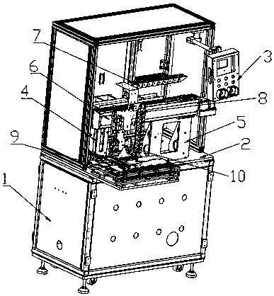
Quick cooling equipment for massive products
A batch product, fast technology, applied in the field of workpiece cooling and cooling, can solve the problems of low safety performance, low production efficiency, product impact, etc., and achieve the effect of good effect, improved production safety, and improved production efficiency.
- Summary
- Abstract
- Description
- Claims
- Application Information
AI Technical Summary
Problems solved by technology
Method used
Image

Examples
Embodiment 2
[0029] Embodiment 2 is different from the above, the feeding device 10 includes a connecting device, a receiving part, a rotating cylinder, and a suction cup assembly, the lower end of the connecting device is fixed to the upper end of the receiving part, and the upper end of the receiving part is connected to the The fixed end of the rotary cylinder, the working end of the rotary cylinder is connected to the upper surface of the suction cup assembly, and the lower surface of the suction cup assembly is fixedly connected to a plurality of suction columns.
Embodiment 3
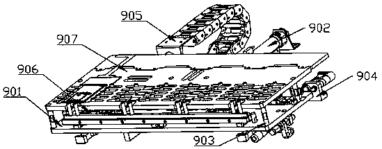
[0030] Embodiment 3 is different from the above, in that a plurality of cleaners are arranged on the side of the second object loading plate 907, and the plurality of cleaners are telescopic to clean the cooled products.
Embodiment 4
[0031]Embodiment 4 is different from the above, the upper surface of the second object loading plate 907 is set to match the lower surface of the product, the working principle of the present invention: firstly, the staff or intelligent robot is connected to the machine through a rotating rod. Set up the operation box on shelf 1, start the device by pressing the on / off key among the several buttons, and then operate the operation keys among the several buttons to watch through the display screen, find the stored system from the storage board on the control panel, and then proceed Adjust the starting equipment. Since the operation box and the transplanting device are in the same position when starting the equipment, it is inconvenient during work. You can rotate the box to the right or above through the rotating rod, and pass the first transplanting device and the second transplanting device of the transplanting device. The second transplanting device moves to drive the feeding ...
PUM
 Abstract
Description
Claims
Application Information