Hydraulic cone crusher

A cone crusher and hydraulic technology, applied in grain processing, climate sustainability, sustainable waste treatment, etc., can solve the problem of large investment in artificial sand, achieve a large crushing ratio, improve quality and effect

Active Publication Date: 2021-05-25
成都卓山机械设备有限公司
4 Cites 0 Cited by

AI-Extracted Technical Summary

Problems solved by technology

[0004] The purpose of the present invention is to provide a hydraulic cone crusher,...

Method used

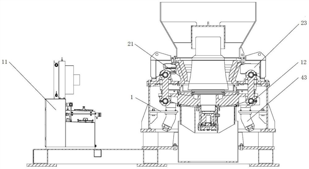
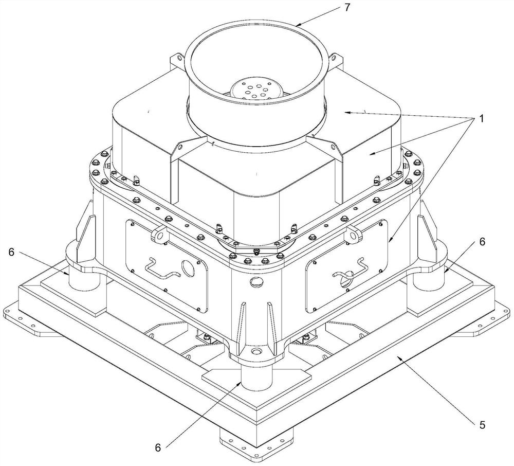
As shown in Figures 1 to 8, a kind of hydraulic cone crusher of the present embodiment includes a casing 1; the casing 1 is covered and arranged on the upper frame assembly, thereby separating the outside world from the space in the casing 1 The separation, on the one hand, increases the aesthetic feeling of the appearance, on the other hand, reduces the erosion of impurities and improves the service life.
Control system 11 is electrically connected to the hydraulic drive assembly; the work of the crusher is remotely controlled, monitoring and correcting the accumulated eccentricity of the upper frame assembly during use, reducing loss and improving the use of Life, and adjust the size of the crushing force to adapt to different crushing needs.
Further, by adjusting the combination of the above two variables, the purpose of adjusting under conditions such as different materials, different feed granularities and different demand granularities can be realized, thereby expanding the scope of use, and also helping to increase the hydraulic cone crusher. Market Competitiveness.
In a kind of possible design, upper frame 21 comprises the frame body that is divided into several layers and several connecting rods that connect adjacent frame body, wherein, the lower side of the bottom frame body is provided with mounting plate 5 , and the frame body is connected to the mounting plate 5 through the elastic member 6; to supplement the structure of the upper frame 21, in view of the height of the rolling socket wall 22 and the lower frame assembly, the frame body needs to be provided with multiple layers. The mounting plate 5 is used to fix the hydraulic cone crusher at the working position or connect it to other equipment. At the same time, in order to prevent the vibration of the hydraulic cone crusher from affecting the stability of the connection during crushing, a set is provided between the mounting plate 5 and the frame. The elastic member 6 absorbs shock and vibration, thereby reducing the vibration of the mounting plate 5 .
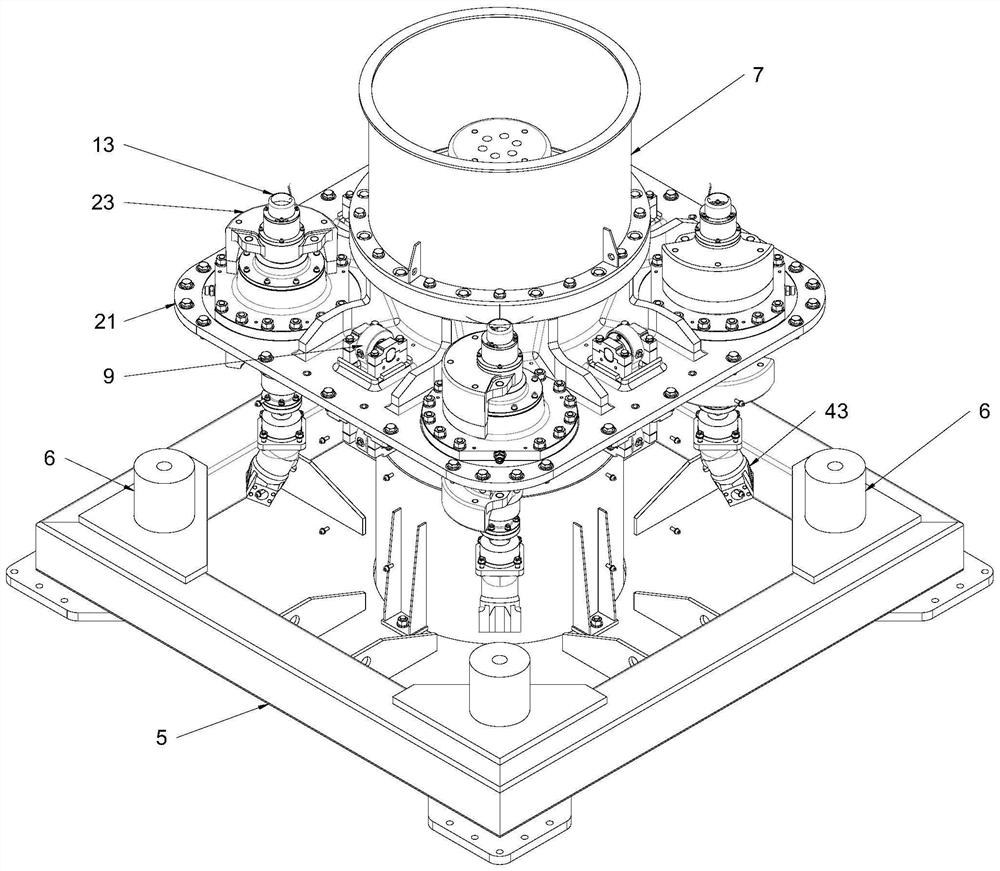
In the specific embodiment provided by the invention, as a kind of selection, as shown in Figure 3-4,8, upper frame assembly is connected to lower frame assembly by suspender structure 9, for suspender structure 9. It ensures that the lower frame assembly can be forced to swing, thereby increasing the absolute value of the crushing force. Specifically, the boom structure 9 includes an upper fixing seat 91 fixed on the upper frame assembly; a lower fixing seat 92 fixed on the lower frame assembly; a boom 93 whose upper end is hinged to the upper fixing seat 91 and whose lower end Hinged to the lower fixing seat 92.
Maximize the reali...

Abstract

The invention provides a hydraulic cone crusher. The hydraulic cone crusher comprises a machine shell, an upper machine frame assembly, a lower machine frame assembly, a hydraulic driving assembly and a control system; the upper machine frame assembly is movably arranged on the machine shell; the lower machine frame assembly is located in the machine shell and movably connected to the upper machine frame assembly; the hydraulic driving assembly is connected to the upper machine frame assembly so as to drive the upper machine frame assembly to swing; and the control system is electrically connected to the hydraulic driving assembly, wherein a crushing cavity used for crushing materials is formed between the upper machine frame assembly and the lower machine frame assembly, and swing of the upper machine frame assembly acts on the materials and is transmitted to the lower machine frame assembly, so that the lower machine frame assembly is forced to swing. The problem of huge investment in the artificial sand crushing process is solved. According to the hydraulic cone crusher, the lower machine frame assembly is driven by the upper machine frame assembly to swing in a forced manner, and the upper machine frame assembly and the lower machine frame assembly form opposite movement in the crushing process, so that the absolute value of crushing force is increased, and the crushing quality and effect are advantageously improved.

Application Domain

Technology Topic

Image

  • Hydraulic cone crusher
  • Hydraulic cone crusher
  • Hydraulic cone crusher

Examples

  • Experimental program(1)

Example Embodiment

[0054] In order to make the purpose, technical solutions and advantages of the embodiments of the present invention clearer, the technical solutions in the embodiments of the present invention will be clearly and completely described below in conjunction with the accompanying drawings in the embodiments of the present invention. Obviously, the described embodiments It is some embodiments of the present invention, but not all of them. The components of the embodiments of the invention generally described and illustrated in the figures herein may be arranged and designed in a variety of different configurations.
[0055] Accordingly, the following detailed description of the embodiments of the invention provided in the accompanying drawings is not intended to limit the scope of the claimed invention, but merely represents selected embodiments of the invention. Based on the implementation manners in the present invention, all other implementation manners obtained by persons of ordinary skill in the art without creative efforts fall within the protection scope of the present invention.
[0056] It should be noted that, in the case of no conflict, the embodiments and features in the embodiments of the present invention can be combined with each other.
[0057] It should be noted that like numerals and letters denote similar items in the following figures, therefore, once an item is defined in one figure, it does not require further definition and explanation in subsequent figures.
[0058]In the description of the present invention, it should be noted that the terms "center", "upper", "lower", "left", "right", "vertical", "horizontal", "inner", "outer" etc. The indicated orientation or positional relationship is based on the orientation or positional relationship shown in the drawings, or the orientation or positional relationship that is usually placed when the product of the invention is used, or the orientation or positional relationship that is commonly understood by those skilled in the art. In order to facilitate the description of the present invention and simplify the description, it does not indicate or imply that the device or element referred to must have a specific orientation, be constructed and operated in a specific orientation, and thus should not be construed as limiting the present invention. In addition, the terms "first", "second", "third", etc. are only used for distinguishing descriptions, and should not be construed as indicating or implying relative importance.
[0059] In the description of the present invention, it should also be noted that, unless otherwise clearly specified and limited, the terms "installation", "installation", "connection" and "connection" should be understood in a broad sense, for example, it may be a fixed connection, It can also be a detachable connection or an integral connection; it can be a mechanical connection or an electrical connection; it can be a direct connection or an indirect connection through an intermediary, and it can be the internal communication of two components. Those of ordinary skill in the art can understand the specific meanings of the above terms in the present invention according to specific situations.
[0060] The present invention will be further elaborated below in conjunction with the accompanying drawings and specific embodiments.
[0061] like Figure 1 to Figure 8 As shown, a hydraulic cone crusher in this embodiment includes a casing 1; the casing 1 is covered and arranged on the upper frame assembly, so as to separate the outside world from the space inside the casing 1, and on the one hand increase the aesthetic feeling of the appearance On the other hand, it reduces the erosion of impurities and improves the service life.
[0062] The upper frame assembly is movable on the casing 1; the upper frame assembly swings under the drive of the hydraulic drive assembly, so as to move relative to the lower frame assembly to crush materials.
[0063] The lower frame assembly is located in the casing 1 and is movably connected to the upper frame assembly; the lower frame assembly is movably connected to the upper frame assembly, so that the upper frame assembly drives the lower frame assembly to swing, The relative movement of the two can increase the crushing force, thereby improving the quality and efficiency of crushed materials.
[0064] The hydraulic drive assembly is connected to the upper frame assembly to drive the upper frame assembly to swing; the hydraulic drive assembly provides a power source for the work of the hydraulic cone crusher, effectively ensuring the crushing work.
[0065] The control system 11 is electrically connected to the hydraulic drive assembly; remotely controls the work of the crusher, monitors and corrects the accumulated eccentricity of the upper frame assembly during use, reduces loss, improves service life, and Adjust the size of the crushing force to adapt to different crushing needs.
[0066] Combining with the structure of this hydraulic cone crusher, the process of crushing materials will be described, in which, a crushing chamber for crushing materials is formed between the upper frame assembly and the lower frame assembly, and the swinging action of the upper frame assembly is used to The material is transferred to the lower frame assembly, so that the lower frame assembly is forced to swing.
[0067] The material enters the hydraulic cone crusher from the upper frame assembly, that is, enters the crushing cavity, and the hydraulic drive assembly drives the upper frame assembly to swing, thereby changing the inner diameter of the crushing cavity, thereby crushing the material. Under the action, the material is crushed and the size of the material is reduced. In addition, the crushing force acts on the lower frame assembly through the transmission of materials. Since the lower frame assembly is movably connected to the upper frame assembly, the lower frame assembly is forced to swing. At the moment of crushing materials, the upper frame assembly The resulting movement is opposite to the movement of the lower frame assembly, thereby increasing the absolute value of the crushing force and helping to improve the quality and effect of crushing.
[0068] The control system 11 monitors the swing of the upper frame assembly, thereby adjusting the power output by the hydraulic drive assembly, thereby adjusting the swing of the upper frame assembly, that is, adjusting the size of the crushing force.
[0069] The hydraulic cone crusher drives the lower frame assembly to swing by the upper frame assembly. During the crushing process, the upper frame assembly and the lower frame assembly form opposite movements, thereby increasing the absolute value of the crushing force. , helps to improve the quality and effect of crushing.
[0070] Maximum realization of lamination crushing; non-directional crushing track makes it easier to find the defect of the material during the crushing process, and use the defect as the crushing port for crushing, so that the least crushing energy can be used to achieve greater crushing ratio.
[0071] Compared with the existing cone crusher, it has the characteristics of larger crushing ratio, energy saving, and can start with load. For example, in the above building material crushing system, it can be changed to a jaw crusher—this hydraulic cone crusher can be crushed in two stages. Realize the original three-stage or four-stage broken effect.
[0072] In the mining industry, the finer the material, the higher the separation efficiency. Its production system is divided into crushing section, grinding section and sorting section. Grinding provides raw materials for sorting, and crushing provides raw materials for grinding. However, in the grinding section, the efficiency of grinding is relatively low, and it is necessary to provide higher power, larger equipment, more infrastructure and personnel to grind out materials that meet the sorting requirements. The concept of "more crushing and less grinding" was put forward under this condition. If the material is crushed as small as possible in the crushing section, it is possible to reduce more investment in the grinding section. The use of this hydraulic cone crusher can maximize the realization of "more crushing and less grinding", thereby saving energy and reducing crushing costs.
[0073] It is easy to understand that this hydraulic cone crusher is explained by taking the mining industry as an example, but the scope of application is not limited to the mining industry, and it can also be used for material crushing operations in building materials, cement or other suitable industries. any restrictions.
[0074] In the specific embodiment provided by the present invention, as an option, the upper frame assembly includes: an upper frame 21, which is connected to the casing 1; on the one hand, the upper frame 21 is connected to the casing 1, and on the other hand For the installation of other components. Preferably, the upper frame 21 can be configured in any suitable structure to adapt to different construction environments, and the present invention does not impose any limitation on this.
[0075] The rolling mortar wall 22 is placed on the upper frame 21; the rolling mortar wall 22 is fixedly connected to the upper frame 21, and the inner wall surface of the rolling mortar wall 22 is provided with several stepped surfaces, thereby helping to improve the crushing effect.
[0076] Optionally, the rolling wall 22 can be made of high manganese steel, high-quality high manganese steel, modified high manganese steel, new high manganese steel, ultra high manganese steel, super strong high manganese steel, metamorphic high manganese steel or other suitable materials Made, the present invention does not make any limitation to this.
[0077] At least two exciters 23 are fixed on the upper frame 21 and are evenly distributed on the outer periphery of the wall 22 of the socket with the wall 22 of the socket as the center. The vibrator 23 acts as a vibrating machine to make the upper frame 21 and the wall 22 connected to the upper frame 21 vibrate, thereby changing the inner diameter of the crushing cavity and realizing the crushing of materials.
[0078] Optionally, according to the size of the upper frame 21, the crushing requirements, the type of the vibrator 23 and other conditions, the number of the vibrator 23 is reasonably selected, and will not be repeated here.
[0079] Now, in combination with the structure of the upper frame assembly, the work of the upper frame assembly in the crushing process is described, wherein, driven by the hydraulic drive assembly, the exciter 23 generates an exciting force, so that the upper frame 21 and the rolling mill The mortar wall 22 vibrates, and the distance between the inner wall surface of the rolling mortar wall 22 and the lower frame assembly changes, that is, the inner diameter of the crushing chamber changes, and the rolling mortar wall 22 exerts a crushing force on the material, so that the rolling mortar wall 22 and the lower frame assembly The frame assembly cooperates to squeeze and crush the material.
[0080] In a possible design, the upper frame 21 includes frame bodies divided into several layers and several connecting rods connecting adjacent frame bodies, wherein, the lower side of the bottom frame body is provided with a mounting plate 5, and the frame body The body is connected to the mounting plate 5 through the elastic member 6; to supplement the structure of the upper frame 21, in view of the height of the rolling wall 22 and the lower frame assembly, the frame body needs to be provided with multiple layers. The mounting plate 5 is used to fix the hydraulic cone crusher at the working position or connect it to other equipment. At the same time, in order to prevent the vibration of the hydraulic cone crusher from affecting the stability of the connection during crushing, a set is provided between the mounting plate 5 and the frame. The elastic member 6 absorbs shock and vibration, thereby reducing the vibration of the mounting plate 5 .
[0081] Optionally, the structure of each layer of the frame can be the same or different, which is selected according to the actual use, and the structure of the frame can also be configured as any suitable structure, which is not limited in the present invention.
[0082] Optionally, the mounting plate 5 is configured as any suitable structure, which is not limited in the present invention.
[0083] Optionally, shock-absorbing springs or other suitable springs and elastomer materials are selected for the elastic member 6; it is easy to understand that those skilled in the art can select the required number of elastic members 6 according to actual use, and details will not be repeated here.
[0084] Correspondingly, the casing 1 is covered and arranged on the adjacent frame body. As for the casing 1, the casing 1 is composed of several casing plates, and the casing plates cover the adjacent frames. For example, the gap between the upper and lower frame bodies is covered by vertically arranged casing plates, and the uppermost frame body The end face is covered with shell plates arranged horizontally, which will not be described in detail here.
[0085] In the specific embodiment provided by the present invention, as an option, the hydraulic drive assembly includes: at least two motors 41 ; the motors 41 provide power to drive the hydraulic pump 42 to work.
[0086] At least two hydraulic pumps 42 are connected to the output end of the motor 41 to drive the hydraulic medium to move; the hydraulic pumps 42 drive the hydraulic medium to move to the hydraulic motor 43 , that is, to transmit force to the hydraulic motor 43 .
[0087] At least two hydraulic motors 43 are connected to the vibration exciter 23 through the coupling 12; the hydraulic motors 43 apply force to the vibration exciter 23 to make the upper frame assembly swing. The coupling 12 plays the role of overload protection and ensures the connection between the hydraulic motor 43 and the vibrator 23 .
[0088] Optionally, any suitable model can be selected for the shaft coupling 12, which is not limited in the present invention.
[0089] Wherein, the motor 41 , the hydraulic pump 42 , the hydraulic motor 43 and the vibration exciter 23 are provided in one-to-one correspondence. It is easy to understand that the respective models of the motor 41 , the hydraulic pump 42 and the hydraulic motor 43 are determined according to actual working conditions, and will not be repeated here.
[0090] The operation of the hydraulic drive assembly will be described, that is, the motor 41 drives the hydraulic pump 42 so that the hydraulic medium enters the hydraulic motor 43 , so that the hydraulic motor 43 and the vibrator 23 work. Wherein, the hydraulic medium is selected from any suitable type of liquid, which is not limited in the present invention.
[0091] In the specific embodiment provided by the present invention, as an option, the control system 11 includes a control terminal and several angular displacement sensors 13 electrically connected to the control terminal. Monitor the rotation angle of the exciter 23; the control terminal is also electrically connected to the hydraulic pump 42 to adjust the flow of hydraulic medium entering the hydraulic motor 43, thereby adjusting the rotation angle of the vibration exciter 23; correspondingly, the hydraulic pump 42 is a variable displacement pump.
[0092] This hydraulic cone crusher drives the rolling wall 22 to swing through the vibration exciter 23, and uses multiple vibration exciters 23 to increase the size of the crushing force, but in the actual use process, due to manufacturing errors and quality differences , flow rate difference and other factors, after long-term use, the vibrator 23 rotates at a certain angle relative to the initial setting position, that is, the vibrator 23 has a rotation angle, which leads to an unbalanced eccentricity of the vibrator 23.
[0093] At this time, for the force applied by a single vibrator 23, the direction of the force changes after the vibrator 23 turns, so that the magnitude and direction of the crushing force change, that is, the crushing effect of the crushing force does not meet expectations, that is, the material The particle size after being crushed by this hydraulic cone crusher does not meet the requirements.
[0094] In this regard, it is improved by setting the control system 11, that is, the angular displacement sensor 13 detects the eccentric angle of the exciter 23 and transmits it to the control terminal, and the control terminal will compare the eccentric angle with the preset angle to obtain the angle difference , when the angle difference is within the set range, that is, the rotation angle of the vibrator 23 is within an acceptable range, there is no need to adjust the position of the vibrator 23 . On the contrary, when the angle difference exceeds the set range, the position of the vibrator 23 needs to be adjusted.
[0095] Specifically, the process of adjusting the position of the vibrator 23 is as follows. The control terminal sends instructions to the hydraulic pump 42 to change the outflow of the hydraulic medium of the hydraulic pump 42, so that the hydraulic motor 43 drives the vibrator 23 to rotate, thereby adjusting the exciter. The angle of the vibrator 23 is within the set range. At the same time, the angular displacement sensor 13 transmits the eccentric angle of the exciter 23 to the control terminal for feedback control.
[0096] On the one hand, the control system 11 realizes remote control of the hydraulic cone crusher, which improves the convenience of use; on the other hand, realizes the adjustment of crushing force, thereby meeting different crushing requirements and expanding the scope of use. At the same time, the control system 11 also makes the multiple vibrators 23 rotate synchronously, which helps to increase the absolute value of the crushing force, reduces internal vibration, and improves the service life.
[0097] Further, the process of adjusting the crushing force is described, that is, when the hydraulic cone crusher is stopped, firstly modify the value of the preset range at the control terminal so that the changed angle of the vibrator 23 is within the range. Secondly, through the transmission chain of the control terminal-hydraulic pump 42-hydraulic motor 43-vibrator 23, the vibrator 23 is rotated to the required direction, thereby adjusting the size of the crushing force, and re-zeroing calibration to reset Determine the initial position of the vibrator 23. Optionally, on the basis of monitoring the rotation of the vibrator 23, the angular displacement sensor 13 is arranged at any suitable position, which is not limited in the present invention.
[0098] Optionally, the hydraulic pump 42 may be any suitable type of variable displacement pump, which is not limited in the present invention.
[0099] In the specific embodiment provided by the present invention, as an option, the lower frame assembly includes: the lower frame 31 is movably connected to the upper frame 21 and is located below the wall of the rolling socket 22; the lower frame 31 is connected to the upper frame The frame 21 provides installation positions for the piston assembly 32 and the moving cone assembly 33 at the same time.
[0100] Optionally, the lower frame 31 can be configured as any suitable structure according to usage conditions, which is not limited in the present invention.
[0101] The piston assembly 32 is fixed on the lower frame 31; on the one hand, the piston assembly 32 provides a placement surface for the moving cone assembly 33, and on the other hand, the piston assembly 32 is connected to the piston cylinder 10, so that the moving cone assembly 33 Slide up and down to adjust the inner diameter of the crushing cavity, so as to facilitate discharge, avoid blockage, and also balance the crushing force, which helps to increase the service life.
[0102] The lower end of the moving cone assembly 33 is placed on the piston assembly 32 , and the upper end passes through the lower frame 31 and is plugged into the wall 22 of the rolling socket. A crushing cavity is formed between the moving cone assembly 33 and the wall 22 of the rolling socket. The moving cone assembly 33 and the rolling socket wall 22 form a crushing chamber to complete the crushing of materials.
[0103] Now combined with the structure of the lower frame assembly, the work of the lower frame assembly in the crushing process will be described, in which, the material is subjected to the crushing force from the wall 22 of the rolling mortar, and the crusher squeezes and crushes the material while passing the material to the The moving cone assembly 33 is then transmitted to the lower frame 31 and the piston assembly 32. Since the lower frame 31 is movably connected to the upper frame 21, the lower frame assembly is forced to swing under the crushing force. At the moment of crushing materials, the movement of the upper frame assembly and the movement of the lower frame assembly are opposite, thus increasing the absolute value of the crushing force and helping to improve the quality and effect of crushing.
[0104] In a possible design, the piston assembly 32 includes a piston cylinder 321 and a piston body 322 slidably disposed in the piston cylinder 321, wherein the upper end of the piston cylinder 321 is fixedly connected to the lower frame 31, and the lower end of the piston cylinder 321 is connected to There is a piston cylinder 10 , and a sealed chamber communicating with the piston cylinder 10 is formed under the piston body 322 .
[0105] The piston body 322 slides up and down in the piston barrel 321 driven by the piston cylinder 10, and the movable cone assembly 33 abutting against the piston body 322 slides up and down along with the piston body 322, thereby adjusting the movable cone assembly 33 and the rolling socket wall 22 The distance between them is the inner diameter of the crushing cavity.
[0106] Optionally, the upper end of the piston barrel 321 is provided with a ring portion for connecting the lower frame 31, and is connected to the lower frame 31 through bolt connection, flange connection or other suitable connection methods, which will not be repeated here.
[0107] In a possible design, the piston cylinder 10 includes an oil cylinder connected to the sealing chamber and a pump body connected to the oil cylinder, and the pump body drives the hydraulic medium in the oil cylinder to flow into the sealing chamber, so that the piston body 322 slides and pushes the starting cone assembly. into 33.
[0108] The structure of the piston cylinder 10 is described, wherein the oil cylinder is connected to the seal chamber, the seal chamber is the part of the piston barrel 321 located below the piston body 322, the hydraulic medium is housed in the oil cylinder, and the pump body is activated to drive the hydraulic medium from the oil cylinder into the seal. cavity, thereby allowing the piston body 322 to slide. On the contrary, after the pump body stops working, the hydraulic medium and the piston body 322 return to the initial position under the action of gravity.
[0109] Optionally, any suitable type can be selected for the oil cylinder and the pump body respectively, which is not limited in the present invention.
[0110] In a possible design, the movable cone assembly 33 includes a main shaft 331 and a movable cone 332 sleeved on the main shaft 331, wherein the lower end of the main shaft 331 is slidably arranged in the piston barrel 321 and abuts against the piston body 322, and the main shaft The upper end of 331 passes through the lower frame 31 and is plugged into the wall 22 of the mortar. The movable cone 332 is at least partly located in the wall 22 of the socket so as to form a crushing cavity with the wall 22 of the socket.
[0111] The structure of the movable cone assembly 33 is supplemented, wherein the main shaft 331 is a part abutting against the piston body 322 , the cross section of the movable cone 332 is conical, and cooperates with the rolling socket wall 22 to form a crushing chamber. When the piston body 322 slides up and down, the main shaft 331 moves accordingly. Preferably, in order to improve the sliding accuracy of the main shaft 331 , the lower frame 31 is provided with a sleeve, and the main shaft 331 is inserted into the sleeve.
[0112] In the specific embodiment provided by the present invention, as an option, such as Figure 3-4 , 8, the upper frame assembly is connected to the lower frame assembly through the boom structure 9, and the boom structure 9 ensures that the lower frame assembly can be forced to swing, thereby improving the absolute value of the crushing force. Specifically, the boom structure 9 includes an upper fixing seat 91 fixed on the upper frame assembly; a lower fixing seat 92 fixed on the lower frame assembly; a boom 93 whose upper end is hinged to the upper fixing seat 91 and whose lower end Hinged to the lower fixing seat 92.
[0113] Optionally, the upper fixing base 91 and the lower fixing base 92 are respectively configured as any suitable structure, and the comparison of the present invention is not limited in any way. Preferably, the upper fixing base 91 and the lower fixing base 92 are constructed with the same structure, so as to save economic cost.
[0114] The upper and lower ends of the suspension rod 93 are all hinged, thereby retaining the degree of freedom of the suspension rod structure 9, so that the lower frame 31 is forced to swing.
[0115] In the specific embodiment provided by the present invention, as an option, the hydraulic cone crusher further includes a feed hopper 7 located above the upper frame assembly and a discharge hopper 8 located below the lower frame assembly, wherein , the feed hopper 7 passes through the casing 1 and communicates with the upper frame assembly. The arrangement of the feed hopper 7 and the discharge hopper 8 ensures the entry and exit of materials, prevents the materials from flowing around, and reduces the pollution of the surrounding environment during the crushing process.
[0116] In the hydraulic cone crusher, the size of the crushing force can be achieved by adjusting the degree of unbalance and eccentricity on the exciter 23 or by adjusting the rotational speed. For eccentric adjustment, for example, as Figure 2-3 As shown, the exciter 23 is set to four and divided into two groups with two diagonals, a total of two groups, the adjustment of the crushing force can be realized by adjusting the angle between any one group of eccentricity and another group of eccentricity, namely Under the condition of the same rotational speed, when the two groups are in the same direction, the angle is considered to be 0°, and the crushing force is the largest; when the eccentricity of the two groups is just opposite, the angle is considered to be 180°, and the crushing force is the smallest; It can be adjusted from 0°-180° to realize the adjustment of crushing force.
[0117] For adjusting the rotating speed, that is, the size of the crushing force is proportional to the square of the angular velocity, and the rotating speed can obviously change the size of the crushing force. Specifically, the motor 41 is configured as a variable frequency motor, so that the stepless speed regulation of the variable frequency motor 41 is realized through the frequency converter. , the higher the speed, the greater the crushing force; the lower the speed, the opposite.
[0118] Furthermore, by adjusting the combination of the above two variables, the purpose of adjustment can be achieved due to different materials, different feed particle sizes and different required particle sizes, thereby expanding the scope of use and also helping to increase the market competitiveness of this hydraulic cone crusher. .
[0119] In addition, it should be noted that the various specific technical features described in the above specific implementation manners may be combined in any suitable manner if there is no contradiction. In order to avoid unnecessary repetition, various possible combinations are not further described in the present invention.
[0120] The present invention is not limited to the above-mentioned optional embodiments, anyone can draw other various forms of products under the enlightenment of the present invention, but no matter make any changes in its shape or structure, any change that falls within the scope of the claims of the present invention The technical solutions within the scope all fall within the protection scope of the present invention.

PUM

no PUM

Description & Claims & Application Information

We can also present the details of the Description, Claims and Application information to help users get a comprehensive understanding of the technical details of the patent, such as background art, summary of invention, brief description of drawings, description of embodiments, and other original content. On the other hand, users can also determine the specific scope of protection of the technology through the list of claims; as well as understand the changes in the life cycle of the technology with the presentation of the patent timeline. Login to view more.

Similar technology patents

Classification and recommendation of technical efficacy words

  • Large crushing ratio
  • Improve quality and performance

Dual-shaft unpacking and breaking device

PendingCN111229408ALarge transmission torqueLarge crushing ratioGrain treatmentsStructural engineeringSpiral line
Owner:NINGBO HUILONG MACHINERY CO LTD

Stone crusher

InactiveCN110237915AReduce dust and noiseLarge crushing ratioGrain treatmentsEngineeringCrusher
Owner:广东金石建材有限公司

Movable-type pharmaceutical raw material comprehensive processing machine

InactiveCN106563558AGood crushing effectLarge crushing ratioGrain treatmentsEngineeringIntegrated processing
Owner:YICHUN WANSHEN PHARMA MACHINERY

Mobile agricultural feed crusher

InactiveCN111229436AIncrease bite angleLarge crushing ratioFeeding-stuffGrain treatmentsElectric machineryAgricultural engineering
Owner:聂丹

Quenching process of H13 steel aluminum alloy die-casting die

InactiveCN106755880AThe quenching process is simpleImprove quality and performanceFurnace typesHeat treatment furnacesQuenchingStress relief
Owner:巴南区伟鹏机械加工厂
Why Eureka
Try Eureka