

Angle pressure device on outer rotor winding machine
A winding machine and outer rotor technology, applied in the direction of electromechanical devices, manufacturing motor generators, electrical components, etc., can solve problems such as loose coils, uneven lead wires, and uneven angles of broken lines, so as to improve performance and improve performance. quality, effect of avoiding dents or wear
- Summary
- Abstract
- Description
- Claims
- Application Information
AI Technical Summary
Problems solved by technology
Method used
Image

Examples
Embodiment 1
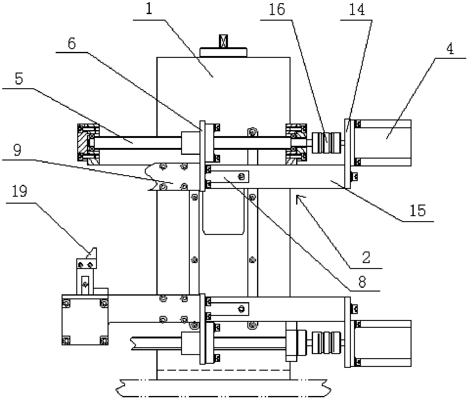
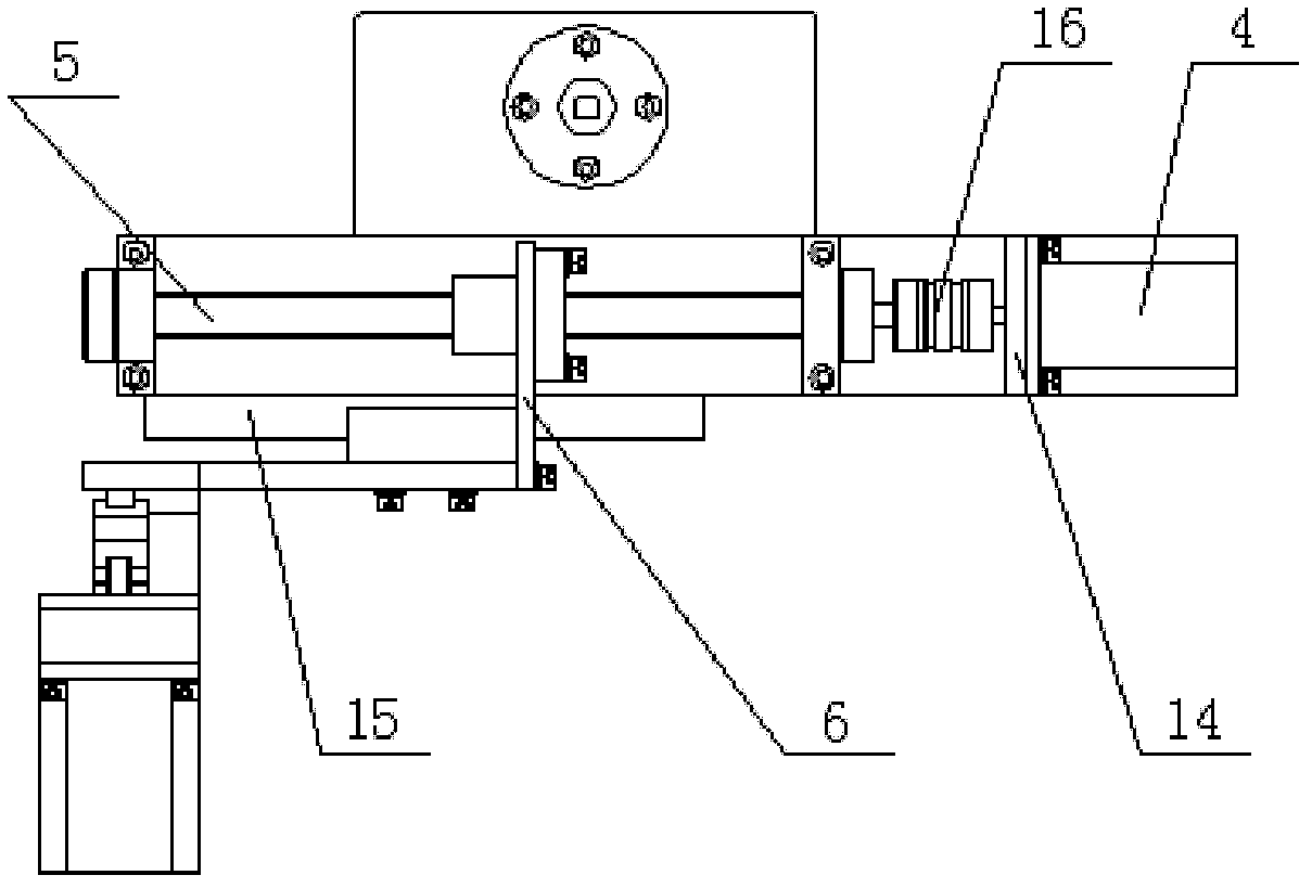
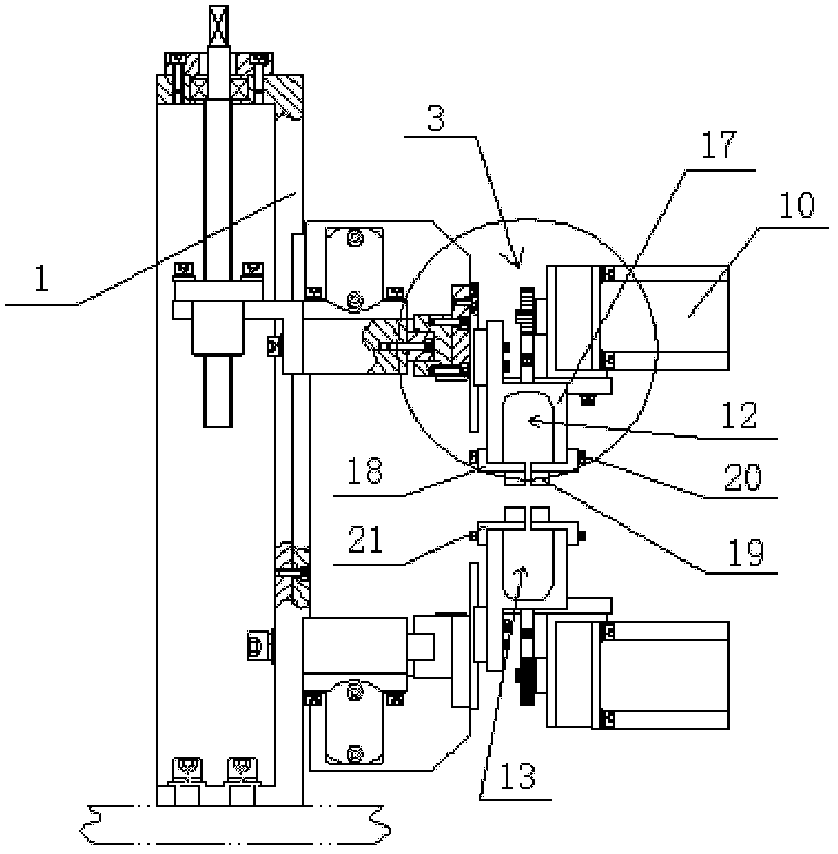
[0019] Embodiment one: see Figure 1~4 As shown, an angle-pressing device on an outer rotor winding machine includes a pair of angle-pressing mechanisms arranged up and down oppositely, which are respectively installed on the main box body 1 of the winding machine. The motion pair 2, the lifting linear motion pair 3 and the pressure angle structure installed on the lifting linear motion pair 3, the forward linear motion pair 2 includes a forward motor 4, a forward ball screw 5 connected with the forward motor 4 , the forward screw connection block 6 screwed on the forward ball screw 5, and the forward guide rail 8 arranged perpendicular to the rotor indexing rotation axis of the winding machine, the forward screw connection block 6 is slidably connected to the forward On the guide rail 8; the lifting linear motion pair 3 is connected with the advance screw connecting block 6 through a guide rail connecting plate 9, and the lifting linear motion pair 3 includes a lifting step...
PUM
 Abstract
Description
Claims
Application Information