Display compensation circuit, display substrate, display device and driving method

A display substrate and compensation circuit technology, applied to static indicators, instruments, etc., can solve problems such as uniformity of display screens and load differences

Active Publication Date: 2021-04-09
BOE TECH GRP CO LTD +1
View PDF10 Cites 0 Cited by
  • Summary
  • Abstract
  • Description
  • Claims
  • Application Information

AI Technical Summary

Problems solved by technology

In the display stage, due to the load difference between the special-shaped common electrode and the normal common electrode, it is easy to cause uniformity problems in the display screen

Method used


Image

  • Display compensation circuit, display substrate, display device and driving method
  • Display compensation circuit, display substrate, display device and driving method
  • Display compensation circuit, display substrate, display device and driving method

Examples


Embodiment Construction

[0029] In order to make the objectives, technical solutions and advantages of the present invention clearer, the embodiments of the present invention will be further described in detail below with reference to the accompanying drawings.

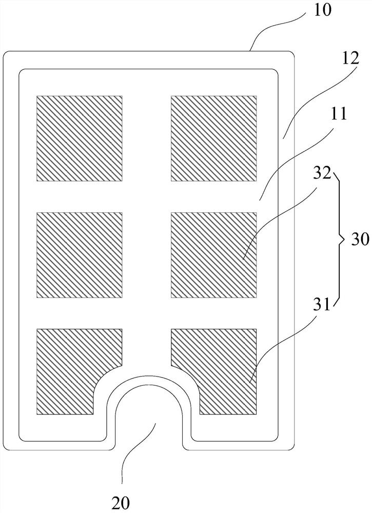
[0030] The display compensation circuit provided in the embodiment of the present invention can be applied to a display substrate provided with structures such as slots, holes, or rounded corners, and these structures can be used to accommodate electronic devices, such as cameras. For ease of understanding, the following combination figure 1 The application scenarios of the embodiments of the present invention are briefly introduced.

[0031] figure 1 It is a schematic structural diagram of a display substrate provided by an embodiment of the present invention. see figure 1 , the display substrate 10 is provided with a U-shaped groove 20, and the U-shaped groove 20 can be used to set the front camera in the mobile terminal. The display su...


PUM


Abstract

The invention discloses a display compensation circuit, a display substrate, a display device and a driving method, and belongs to the field of display technology. The display compensation circuit includes: a switch subcircuit; each of the switch subcircuits has an input terminal, an output terminal and a control terminal; the output terminal of the switch subcircuit is electrically connected to one of the first common electrodes; the switch subcircuit The circuit is configured to be turned on under the control of the control signal received by the control terminal, and to provide the compensation voltage signal received by the input terminal to the corresponding first common electrode when it is turned on. The display uniformity problem caused by the load difference between the first common electrode and the second common electrode is solved.

Description

technical field [0001] The present invention relates to the field of display technology, and in particular, to a display compensation circuit, a display substrate, a display device and a driving method. Background technique [0002] With the technological development of mobile terminals, the screen ratio of mobile terminals is increasing. When the screen ratio of the mobile terminal reaches a certain size, a slot or a hole needs to be formed on the screen of the mobile terminal to set the front camera. [0003] For touch screens and other screens that divide the common electrodes into multiple common electrodes for function multiplexing, since most of the slots or holes on the screen where the front camera is set are U-shaped or circular, when the screen is fabricated, the holes or holes located in the slots or holes are mostly U-shaped or circular. The nearby common electrode needs to be shaped to match the shape of the slot or hole. [0004] Compared with the normal comm...

Claims


Application Information

Patent Timeline
Patent Type & Authority Patents(China)
IPC IPC(8): G09G3/20
CPCG09G3/20
Inventor 张文龙于亚楠徐敬义姜瑞泽石天雷吴治涌
Owner BOE TECH GRP CO LTD
Why Eureka
Try Eureka