Method for measuring axial clearances of bilateral dislocation differential confocal mirror groups

A differential confocal and axial gap technology, which is applied to measuring devices, instruments, and optical devices, can solve problems such as system structure, complex assembly process, and large errors, so as to improve capture accuracy, high-precision measurement, The effect of improving the focus accuracy

Active Publication Date: 2019-06-14
BEIJING INSTITUTE OF TECHNOLOGYGY
View PDF8 Cites 2 Cited by
  • Summary
  • Abstract
  • Description
  • Claims
  • Application Information

AI Technical Summary

Problems solved by technology

This method has the advantages of high measurement accuracy and fast measurement speed, but it must use two detectors, and the positions of the two detectors must ensure that the defocus amount is equal. The system structure and installation process are more complicated, and the installation and adjustment are not accurate. The error introduced may be large; after the lens group under test is replaced, the defocus of the two detectors may need to be readjusted

Method used


Image

  • Method for measuring axial clearances of bilateral dislocation differential confocal mirror groups
  • Method for measuring axial clearances of bilateral dislocation differential confocal mirror groups
  • Method for measuring axial clearances of bilateral dislocation differential confocal mirror groups

Examples


Embodiment

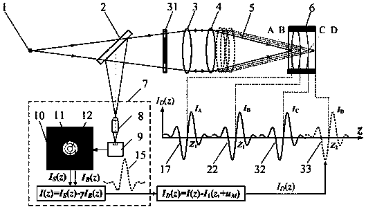
[0049] achieve attached figure 1 The implementation device of the axial gap measurement method of the bilateral misalignment differential confocal lens group is as follows: Figure 6 As shown, the measurement steps are:

[0050] a) Start the measurement software of the main control computer 24, turn on the laser 28, and the light emitted by the laser 28 passes through the microscope objective lens 29 and the pinhole 30 to form a point light source 1.

[0051] b) Adjust the measured lens group 6 so that it has the same optical axis as the measuring objective lens 4 and the collimating lens 3, the light emitted by the point light source 1 passes through the beam splitter 2, the collimating lens 3 and the measuring objective lens 4, and then converges into a measuring beam 5 to focus On the measured mirror group 6, the focused measurement beam 5 reflected by the measured mirror group 6 is reflected by the beam splitter 2 after passing through the measuring objective lens 4 and c...


PUM


Abstract

The invention discloses a method for measuring axial clearances of bilateral dislocation differential confocal mirror groups, and belongs to the technical field of optical precision measurement. According to the method, a small virtual pinhole detection area and a small virtual pinhole detection area are firstly set on an Airy disk image detected by a CCD in a confocal measurement system, and subtraction is carried out on two detected confocal characteristic curves to sharpen the confocal characteristic curves; bilateral dislocation differential subtraction is carried out on the sharpened confocal characteristic curves to obtain axial high-sensitivity differential confocal characteristic curves; characteristics accurately corresponding to zero points of the bilateral dislocation differential confocal characteristic curves and a focus of the confocal measurement system are utilized to carry out high-precision focus fixing and locating on inner and outer peak positions of a measured mirror group; and finally ray tracing compensation calculation is carried out to accurately obtain an axial clearance of the measured mirror group. Compared with the existing mirror group clearance measurement methods, the method provided by the invention has the advantages of being high in measurement precision, strong in environment interference resistance and simple in structure, and has a wide application prospect in the technical field of optical precision measurement.

Description

technical field [0001] The invention relates to a method for measuring the axial gap of a bilateral dislocation differential confocal lens group, which can be used for non-contact high-precision measurement of the lens group gap and belongs to the technical field of optical precision measurement. Background technique [0002] In the field of optics, the measurement of the lens group gap is of great significance. During the assembly process of high-performance optical systems such as lithography objective lenses and aerospace cameras, it is necessary to precisely adjust the lens axial gap, radial offset and optical axis deflection angle according to the curvature radius and refractive index of the lens in the lens. Taking the objective lens of lithography machine as an example, the axial gap deviation of each single lens will cause spherical aberration, astigmatism, coma, distortion and other aberrations of the lithography objective lens, which will affect the imaging quality...

Claims


Application Information

Patent Timeline
Patent Type & Authority Applications(China)
IPC IPC(8): G01B11/14
Inventor 赵维谦邱丽荣
Owner BEIJING INSTITUTE OF TECHNOLOGYGY
Why Eureka
Try Eureka