Light waveguide and display device

A technology of optical waveguide and grating, which is applied in the field of optical waveguide and display equipment, and can solve the problems that the optical waveguide cannot be satisfied at the same time.

Inactive Publication Date: 2019-06-18
BOE TECH GRP CO LTD
View PDF6 Cites 23 Cited by
  • Summary
  • Abstract
  • Description
  • Claims
  • Application Information

AI Technical Summary

Problems solved by technology

[0005] In order to solve the above-mentioned technical problems, the present invention provides an optical waveguide and a display device to solve the two requirements of the optical waveg

Method used


Image

  • Light waveguide and display device
  • Light waveguide and display device
  • Light waveguide and display device

Examples


Embodiment Construction

[0042] In order to make the purpose, technical solutions and advantages of the embodiments of the present invention more clear, the following will clearly and completely describe the technical solutions of the embodiments of the present invention in conjunction with the drawings of the embodiments of the present invention. Apparently, the described embodiments are some, not all, embodiments of the present invention. All other embodiments obtained by those skilled in the art based on the described embodiments of the present invention belong to the protection scope of the present invention.

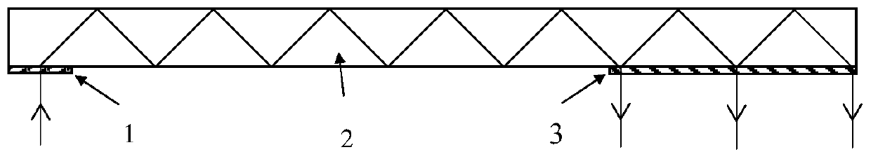
[0043] The technical principle of holographic optical waveguide 2 is as follows: figure 1 As shown: the incident light is coupled into the optical waveguide 2 after being diffracted by the grating 1. When the diffraction angle of the beam is smaller than the critical angle of total reflection of the optical waveguide 2, the light beam will propagate forward in the form of total reflection i...


PUM


Abstract

The invention relates to a light waveguide. The light waveguide includes a light waveguide body, wherein the light waveguide body includes a beam coupling-in region and a beam coupling-out region, thebeam coupling-in region is provided with a coupling-in grating and configured to couple a beam into the light waveguide body and make the beam propagate in the light waveguide body in a totally reflective manner, the beam coupling-out region is provided with a coupling-out grating, is configured to couple the beam propagated to the beam coupling-out region out of the light waveguide body and makes the beam not undergo secondary diffraction at the coupling-in the grating and has a continuous expansion exit pupil, and the coupling-out grating includes a transmissive coupling-out grating and a reflective coupling-out grating disposed on two sides of the light waveguide body parallel to the beam propagation direction. The invention further relates to a display device. Through arranging the transmissive coupling-out grating at the light outgoing surface of the light waveguide body and the reflective coupling-out grating on the first surface, the continuous expansion exit pupil can be obtained while the beam is guaranteed not undergo secondary diffraction at the coupling-in the grating.

Description

technical field [0001] The invention relates to the field of display technology, in particular to an optical waveguide and a display device. Background technique [0002] Augmented reality technology (Augmented Reality, AR) display device can integrate the real background environment while displaying virtual image information, and realize the organic combination of virtual and reality. field has been widely used. AR display devices are mainly head-mounted, so devices are required to be thinner and lighter to meet long-term wearing comfort. Among the various implementation schemes of AR display devices, holographic optical waveguide technology uses slab waveguide as the light propagation medium and holographic element as the optical path folding device. It has the advantages of simple structure, light weight and small size, and is the key to the next generation of AR display. technology. [0003] The technical principle of the holographic optical waveguide is as follows: t...

Claims


Application Information

Patent Timeline
IPC IPC(8): G02B27/01G02B6/124
CPCG02B27/0172G02B2027/0125G02B27/0081G02B6/34G02B6/0055
Inventor 马森
Owner BOE TECH GRP CO LTD
Why Eureka
Try Eureka