

Traction mechanism of self-propelled vehicle and self-propelled vehicle
A traction mechanism and self-propelled technology, applied in traction connectors, vehicle components, transportation and packaging, etc., can solve problems such as inability to flexibly steer
- Summary
- Abstract
- Description
- Claims
- Application Information
AI Technical Summary
Problems solved by technology
Method used
Image

Examples
Embodiment 1
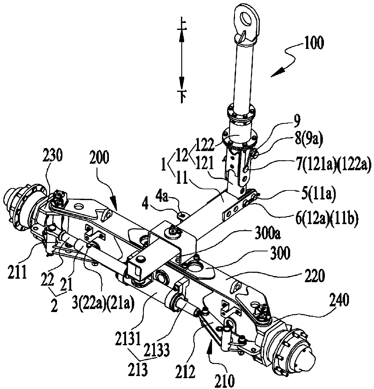
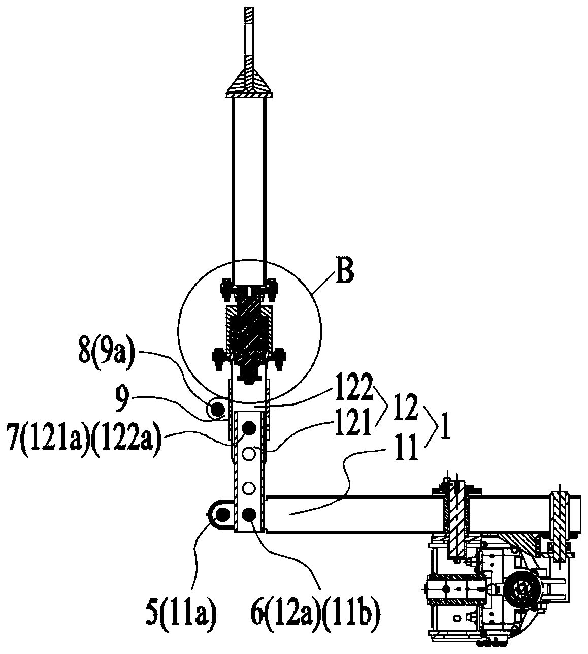
[0047] Embodiment 1 of the present invention provides a traction mechanism for a self-propelled vehicle. Such as figure 1 and figure 2 As shown, the traction mechanism 100 includes a rotating connection assembly 1 , a telescoping mechanism 2 and a first locking member 3 . The rotating connection assembly 1 is rotatably connected with the first end of the telescopic mechanism 2, and the second end of the telescopic mechanism 2 is rotatably connected with the steering mechanism 210 of the axle 200 of the self-propelled vehicle. The first locking member 3 is used to lock the telescopic mechanism 2 In order to limit the expansion and contraction of the telescopic mechanism 2, the rotating connection assembly 1 can drive the locked telescopic mechanism 2 to drive the steering mechanism 210 to turn.
[0048] Specifically, when the first locking member 3 is in the unlocked state, the traction mechanism 100 is in the non-working state, and the self-propelled vehicle mainly relies o...
Embodiment 2
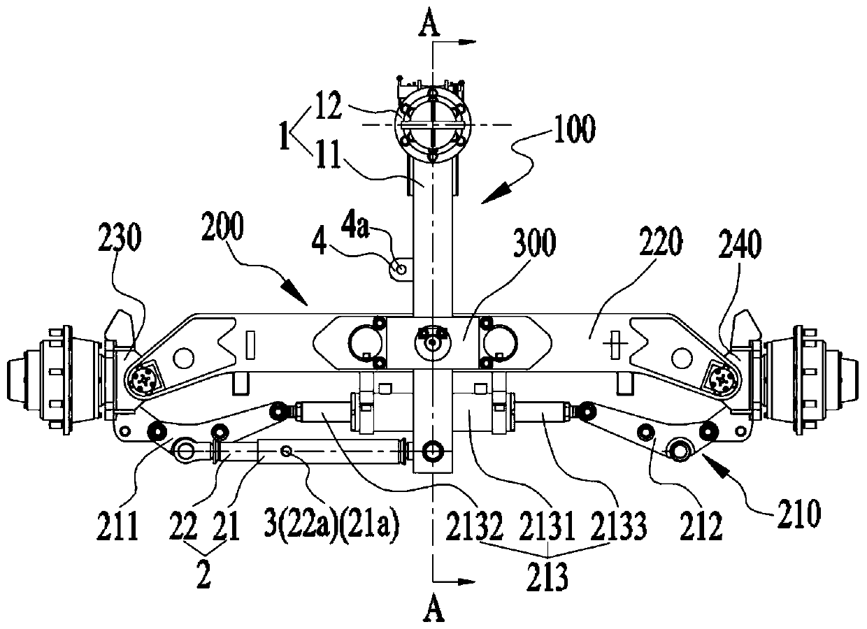
[0062] Embodiment 2 of the present invention provides a self-propelled vehicle, such as Figure 5 and Figure 6 As shown, the self-propelled vehicle includes an axle 200 and the traction mechanism 100 provided in Embodiment 1. The axle 200 includes a crossbeam 220 and a steering mechanism 210 mounted on the crossbeam 220. The rotating connection assembly 1 is rotationally connected with the crossbeam 220. The telescopic mechanism The second end of 2 is rotatably connected with the steering mechanism 210.
[0063] Further, combine Figure 1-2 As shown, the self-propelled vehicle also includes a mounting base 300, the mounting base 300 is arranged on the beam 220, the rotating connection assembly 1 is rotationally connected with the beam 220 through the mounting base 300, the mounting base 300 includes a limiting hole 300a, and one end of the rotating connecting assembly 1 It passes through the limiting hole 300a and is rotatably connected with the first end of the telescoping...
PUM
 Abstract
Description
Claims
Application Information