Household medical shaping treadmill

A treadmill and medical technology, which is applied in the field of medical equipment, can solve the problems of poor stability and the inability of the treadmill to perform medical shaping, etc., and achieve the effects of improving stability, improving body coordination, and good cushioning effect

Inactive Publication Date: 2019-07-05
樊燕龙
View PDF6 Cites 0 Cited by
  • Summary
  • Abstract
  • Description
  • Claims
  • Application Information

AI Technical Summary

Problems solved by technology

[0005] The purpose of the present invention is to provide a household medical shaping treadmill that can play a role in shaping and has good stability in view of the problem that the existing treadmills cannot achieve the effect of medical shaping and have poor stability.

Method used


Image

  • Household medical shaping treadmill
  • Household medical shaping treadmill
  • Household medical shaping treadmill

Examples


Embodiment 1

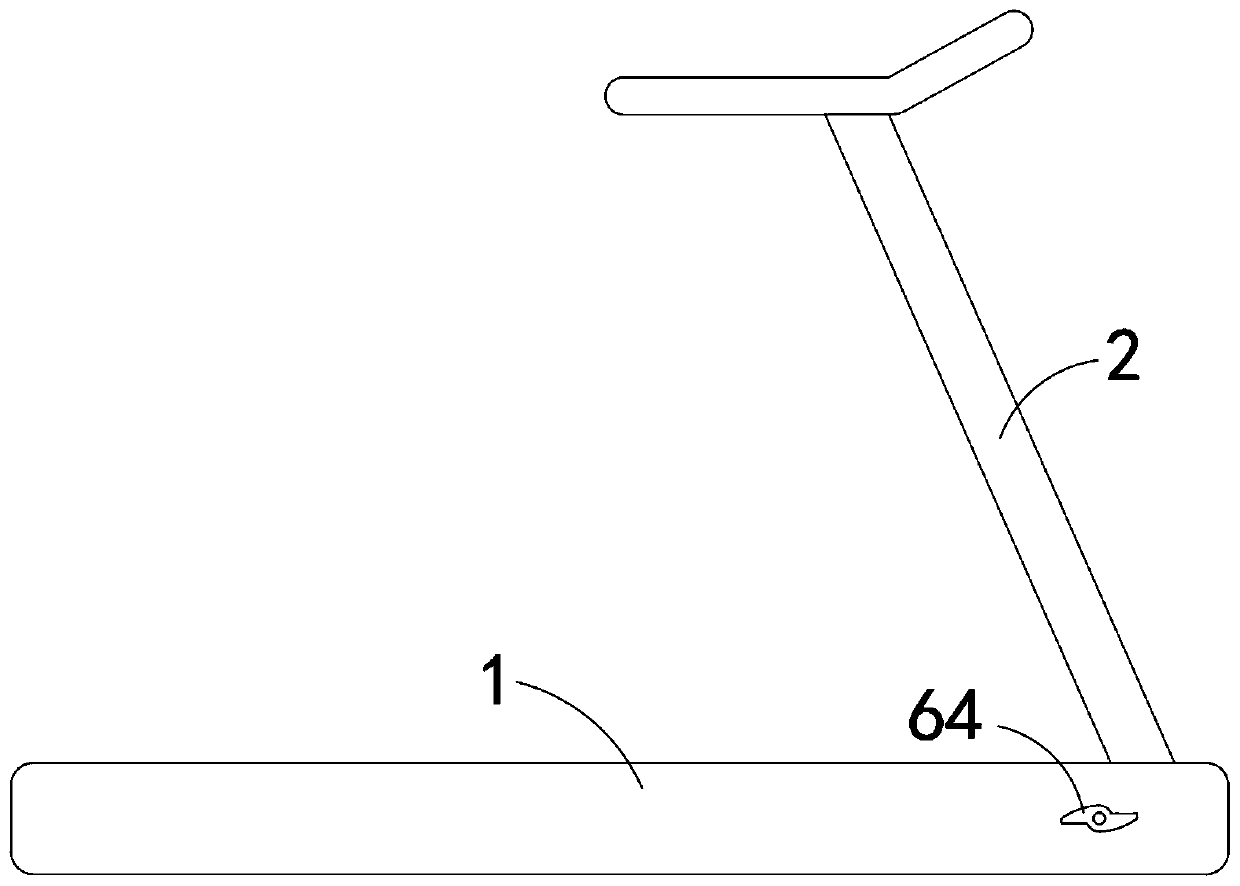
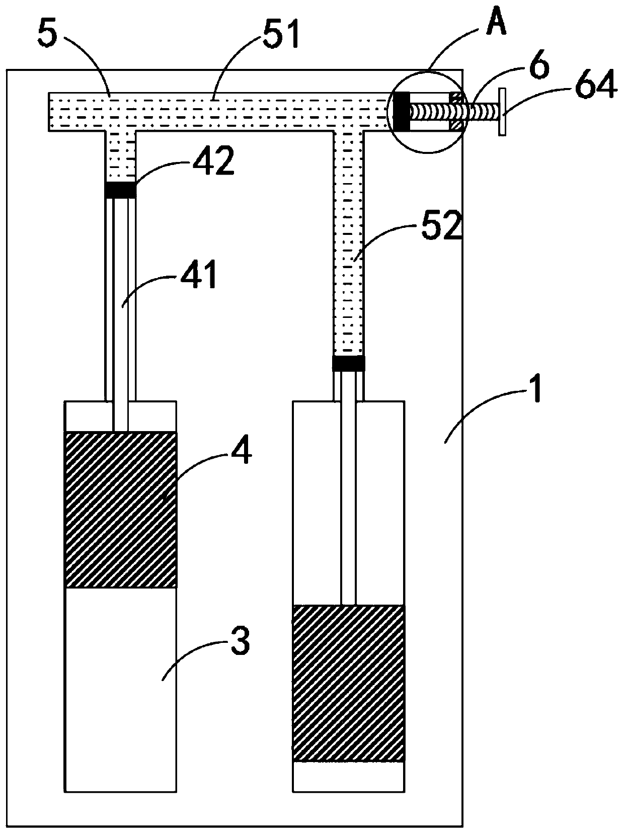
[0023] like Figure 1-3 As shown, a household medical shaping treadmill includes a base 1 and an armrest 2, the armrest 2 is fixedly connected to the upper end of the base 1, the left and right sides of the base 1 are provided with sliding grooves 3, and the sliding grooves 3 are arranged on the bottom of the base 1. The upper surface, and the sliding groove 3 is a bar-shaped chute, the sliding groove 3 is provided with a pedal 4, the left and right side walls of the pedal 4 are slidingly connected with the side walls of the sliding groove 3, and the upper end of the pedal 4 is connected to the upper surface of the base 1 flush, so that the pedal 4 can be hidden in the base 1 to avoid accidental bumps. The upper surface of the pedal 4 is provided with a non-slip mat, which can be made of rubber and other materials.

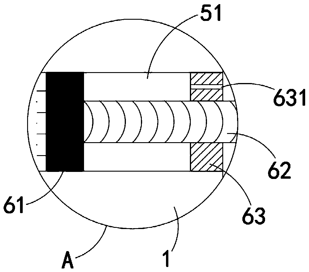
[0024] The base 1 is provided with a communication cavity 5, the communication cavity 5 includes a main passage 51 and two branch passages 52, the main passage 51...

Embodiment 2

[0030] like Figure 4-5 As shown, the difference between this embodiment and Embodiment 1 is that a buffer mechanism 7 connected to the pedal 4 is provided in the slide groove 3, and the buffer mechanism 7 includes an elastic air bag 71, which is sleeved outside the connecting rod 41, And the two ends of the elastic airbag 71 are respectively fixedly connected with the side walls of the sliding groove 3 and the pedal 4, and a plurality of suction cups 8 are arranged on both sides of the lower end of the base 1, and the buffer mechanism 7 communicates with the suction cups 8. Specifically, the base 1 A connecting main pipe 72 is provided, and a plurality of suction cups 8 are connected with the communicating main pipe 72 , and the elastic airbag 71 is connected with the communicating main pipe 72 through a communicating branch pipe 73 .

[0031] In this embodiment, by setting the elastic airbag 71, the connecting rod 41 can be completely wrapped, reducing the impact of external...


PUM


Abstract

The invention belongs to the field of medical instruments and particularly relates to a household medical shaping treadmill, which comprises a base and handrails. Sliding grooves are formed in the left side and the right side of the base. Pedals are arranged in the sliding grooves in a sliding mode. A communicating cavity is formed in the base. The two pedals are in linkage with each other throughthe communicating cavity. An adjusting mechanism used for adjusting the volume of the communicating cavity is further arranged on the side wall of the base. Buffering mechanisms connected with the pedals are arranged in the sliding grooves. A plurality of suckers are arranged on the two sides of the lower end of the base and are communicated with the buffering mechanisms. According to the invention, the left and right pace distances of a user can be kept consistent. Therefore, medical treatment and shaping effects are achieved. By arranging an elastic air bag, a connecting rod can be completely wrapped by the elastic air bag. Therefore, the influence of external dust or sundries on the connecting rod is reduced. A good buffering effect can be achieved. The collision between the pedals andthe sliding grooves is reduced. The suckers can be firmly adsorbed to the ground, and the effect of improving the stability of the base is achieved.

Description

technical field [0001] The invention belongs to the field of medical equipment, in particular to a household medical shaping treadmill. Background technique [0002] Treadmill is a common fitness equipment for families and gyms, and it is the simplest type of home fitness equipment today, and it is the best choice for home fitness equipment. [0003] Most of the existing treadmills are belt-type treadmills, which are driven by the friction between the runner and the belt and continue to run. However, for some people with uncoordinated bodies, the belt-type treadmill cannot correct them. Can not play the effect of medical treatment and shaping. [0004] For this reason, we propose a kind of household medical plastic treadmill to solve the above problems. Contents of the invention [0005] The purpose of the present invention is to provide a household medical shaping treadmill that can play a role in shaping and has good stability in view of the problem that the existing t...

Claims


Application Information

Patent Timeline
Patent Type & Authority Applications(China)
IPC IPC(8): A63B22/04
CPCA63B22/04A63B2225/055
Inventor 刘毅峰
Owner 樊燕龙
Why Eureka
Try Eureka