
Liquid ejecting head, liquid ejecting unit, and liquid ejecting apparatus

A technology of liquid jet head and nozzle, applied in printing and other directions, to achieve the effect of effective monitoring and position alignment

Active Publication Date: 2019-07-05
RICOH KK
View PDF11 Cites 0 Cited by
  • Summary
  • Abstract
  • Description
  • Claims
  • Application Information

AI Technical Summary

Problems solved by technology

[0004] However, there is a problem that monitoring of the application state of the adhesive and alignment must be performed efficiently when bonding head components with an adhesive while recognizing the mark for position alignment (alignment mark).

Method used


Image

  • Liquid ejecting head, liquid ejecting unit, and liquid ejecting apparatus
  • Liquid ejecting head, liquid ejecting unit, and liquid ejecting apparatus
  • Liquid ejecting head, liquid ejecting unit, and liquid ejecting apparatus

Examples


Embodiment Construction

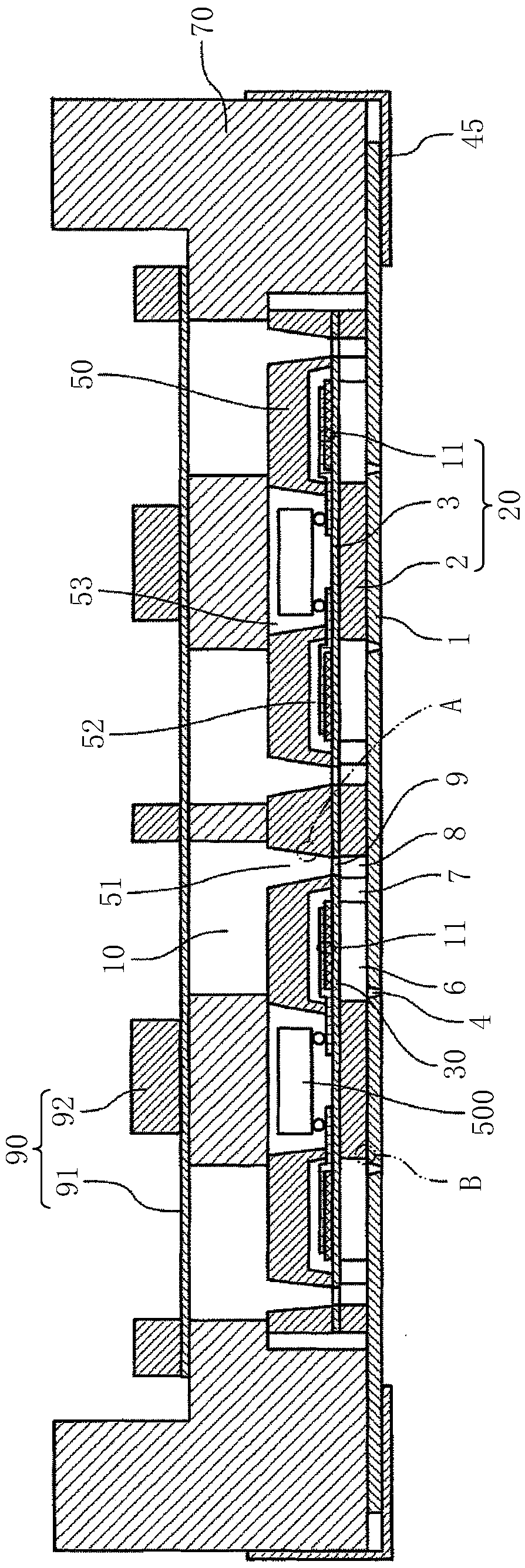
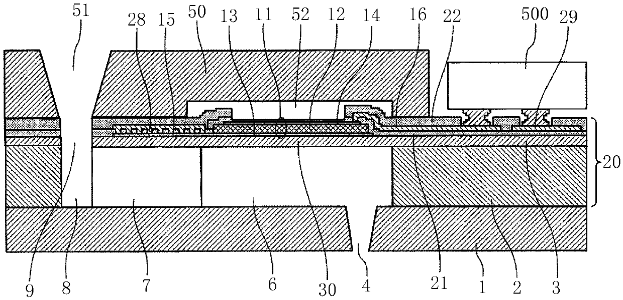
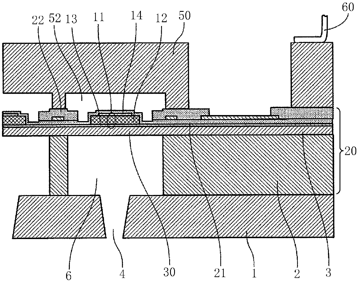
[0027] Hereinafter, embodiments of the present invention will be described with reference to the drawings. Regarding the first embodiment of the liquid discharge head according to the present invention, refer to Figure 1 to Figure 3 to illustrate. figure 1 is a cross-sectional explanatory diagram along a direction perpendicular to the nozzle arrangement direction of the shower head, figure 2 yes figure 1 Explanatory drawing of enlarged cross-section of main part, image 3 It is a cross-sectional explanatory view of main parts along the nozzle arrangement direction of the head.

[0028] The liquid discharge head 100 includes a nozzle plate 1, a flow channel plate 2, a vibration plate member 3 as a wall member, a piezoelectric element 11 as a pressure generating element, a holding base plate 50, a wiring member 60 such as an FPC, and a common liquid chamber member 70. , Cover member 45 .

[0029] Here, the portion constituted by the flow channel plate 2 , the vibrating pl...


PUM


Abstract

The present invention relates to a liquid ejecting head, a liquid ejecting unit, and a liquid ejecting apparatus that efficiently perform monitoring of an adhesive application state and alignment. Theadhesive bonding device comprises a first member (101) and a second member (102) bonded to the first member (101) with an adhesive (103), wherein the first member (101) is provided with a through hole mark (111) as a position alignment mark, and the second member (102) is provided with a first mark (121) and a second mark (122) as position alignment marks, wherein the first mark (121) is a position alignment mark provided with the adhesive (103) in the vicinity of a bonding region (104), and the second mark (122) is a position alignment mark provided with no adhesive (103) in the vicinity ofa region outside the bonding region (104).

Description

technical field [0001] The present invention relates to a liquid spray head, a liquid spray unit and a liquid spray device. Background technique [0002] The liquid discharge head is provided with an alignment mark (alignment mark: Alignment Mark) when bonding a plurality of discharge head constituent members with an adhesive. [0003] Then, for example, two kinds of adhesives are applied to at least one of the first member and the second member to be bonded to each other, and the members are held by the first holding mechanism and the second holding mechanism to face each other, so that each member After contacting each other, pressurize with a weak pressure, contact and press the other part with respect to one part as a reference, keep the posture in the state where the parts are in close contact with each other, and press the The alignment marks provided on each part are used to perform the relative position alignment of each part. After the position is aligned, once the...

Claims


Application Information

Patent Timeline
Patent Type & Authority Applications(China)
IPC IPC(8): B41J2/14
CPCB41J2/14233B41J2/1433B41J2002/14362
Inventor 林启辅
Owner RICOH KK
Learn More