Omni-directional vision mirror system

An all-round, sight-mirror technology, applied in the field of vehicle engineering, can solve the problems of blind spots, poor streamline, and large wind resistance for drivers, and achieve the effect of improving aesthetics and spaciousness, reducing vehicle scraping accidents, and reducing fuel consumption.

Pending Publication Date: 2019-07-12
于樟
View PDF0 Cites 0 Cited by
  • Summary
  • Abstract
  • Description
  • Claims
  • Application Information

AI Technical Summary

Problems solved by technology

[0003] For this reason, the embodiment of the present invention provides a kind of all-round viewing mirror system, to solve the driver's blind spot caused by the small visual range of the reflector in the prior art, easy to scratch and wind resistance due to the installation of the reflector. Big, poorly streamlined issues

Method used


Image

  • Omni-directional vision mirror system
  • Omni-directional vision mirror system

Examples


Embodiment 1

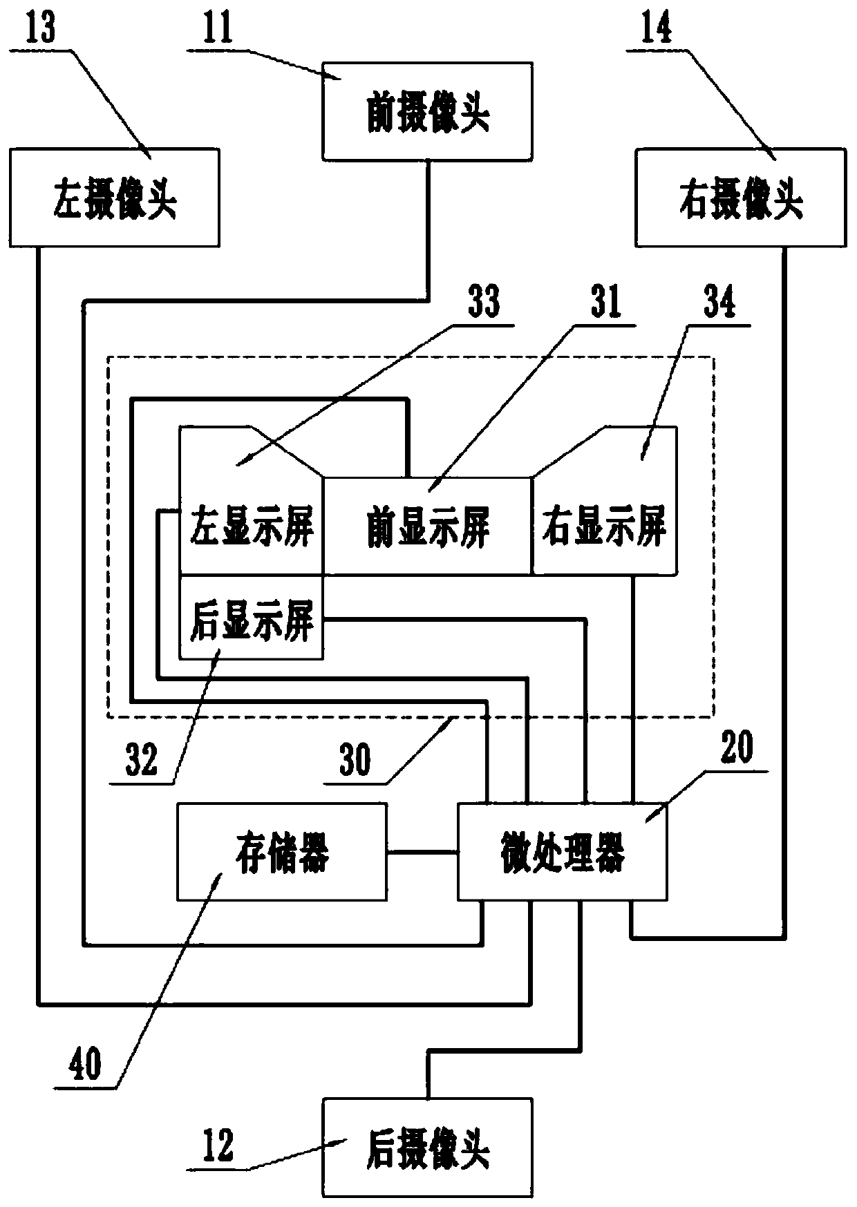
[0022] like figure 1 As shown, Embodiment 1 provides an omnidirectional mirror system, which includes a camera device, a microprocessor 20 , a display device 30 and a memory 40 . The imaging device, the imaging device, the display device 30 and the memory 40 are electrically connected to the microprocessor 20 respectively, and the microprocessor 20, the memory 40 and the display device 30 are all arranged in the car, and the display device 30 can be integrated on the instrument panel or can be separately It is arranged on the front panel on the instrument panel, wherein the camera device is used to collect pictures of the surrounding environment of the vehicle, and the microprocessor 20 is used to transmit the pictures collected by the camera device to the display device 30 and the memory 40, and the display device 30 uses In order to display the images captured by the imaging device, the memory 40 is used to store the images captured by the imaging device. Among them, the di...

Embodiment 2

[0031] Embodiment 2 provides another omnidirectional mirror system, which is basically the same as the omnidirectional mirror system provided by Embodiment 1. The difference is that there are two front cameras installed above the left and right headlights of the vehicle respectively. , the front display screen is divided into left and right screens to display the picture information taken by two front cameras; the rear camera is provided with two, one of which is in the same position as the rear camera in embodiment 1, and the other is installed near the roof of the car, preferably built into the car. Inside, the rear display screen displays the images captured by the two rear cameras in the upper and lower screens. In this embodiment, the microprocessor uses a 6-channel or 8-channel video capture card.

[0032] The omni-directional mirror system provided in this embodiment can more comprehensively and clearly display the existing blind spots of the vehicle and improve driving...


PUM


Abstract

The embodiment of the invention discloses an omni-directional vision mirror system, and relates to the technical field of vehicle engineering. The omni-directional vision mirror system comprises a camera shooting device, a microprocessor and a display device, the camera shooting device and the display device are both electrically connected with the microprocessor, the camera shooting device comprises a front camera installed on the front part of a vehicle, a rear camera installed on the rear part of the vehicle, a left camera installed on the left side of the vehicle, and a right camera installed on the right side of the vehicle, and the display device comprises a front display screen, a rear display screen, a left display screen and a right display screen. According to the omni-directional vision mirror system provided by the embodiment, the two drive blind areas on the front lower part and the rear part of the vehicle are clearly visible, the incidence of the vehicle scraping accidents caused by reflectors are further effectively decreased, in addition, the streamline, attractiveness and spaciousness of the vehicle are improved advantageously, wind resistance is reduced, and fuelconsumption is lowered; and furthermore, the real-time recording function is further achieved, and subjective and objective issues happened around motor vehicles are clarified conveniently.

Description

technical field [0001] The embodiment of the present invention relates to the technical field of vehicle engineering, in particular to an omnidirectional mirror system. Background technique [0002] Motor vehicles are tools commonly used in production and life. When driving a motor vehicle normally, especially when driving on a highway or in a downtown area, the driver needs to look left and right and be highly concentrated. The reflectors (commonly known as "ears") on both sides of the existing motor vehicle are used to assist the driver to observe the situation around the vehicle, but the reflectors can only be installed on both sides of the vehicle at the front position of the cab due to the limited visual range. , the driver cannot fully observe the surrounding environment of the vehicle, and the driver still has many blind spots, such as the underside and rear side of the front of the vehicle. Blind spots will lead to accidents; reflectors are easy to scratch when two...

Claims


Application Information

Patent Timeline
IPC IPC(8): B60R1/00B60R11/02
CPCB60R1/00B60R11/0211B60R11/0229B60R2300/105B60R2300/20B60R2300/802
Inventor 于樟
Owner 于樟
Why Eureka
Try Eureka