Crimp for connecting wires

A technology for connecting wires and crimping parts, which is applied in the direction of connecting components, connections, and connections where permanent deformation acts, and can solve problems such as difficult cutting, bending or forming, inability to prevent deflection of crimping barrels, mechanical and electrical performance failures, etc.

Pending Publication Date: 2019-07-19
TE CONNECTIVITY INDIA +1
View PDF5 Cites 2 Cited by
  • Summary
  • Abstract
  • Description
  • Claims
  • Application Information

AI Technical Summary

Problems solved by technology

Especially for large wire sizes, this minimum barrel stock thickness creates disadvantages because it is difficult to cut, bend or form in the stamping process to manufacture electrical components from sheet metal, and requires high crimping forces and entails high material costs
[0016] On the other hand, when using too thin stock, the crimp st

Method used


Image

  • Crimp for connecting wires
  • Crimp for connecting wires
  • Crimp for connecting wires

Examples


Embodiment Construction

[0040] Before describing the embodiments of the present disclosure, basic knowledge forming the basis of the present disclosure is described. Based on the foregoing considerations, the inventors have conceived the following aspects of the present disclosure.

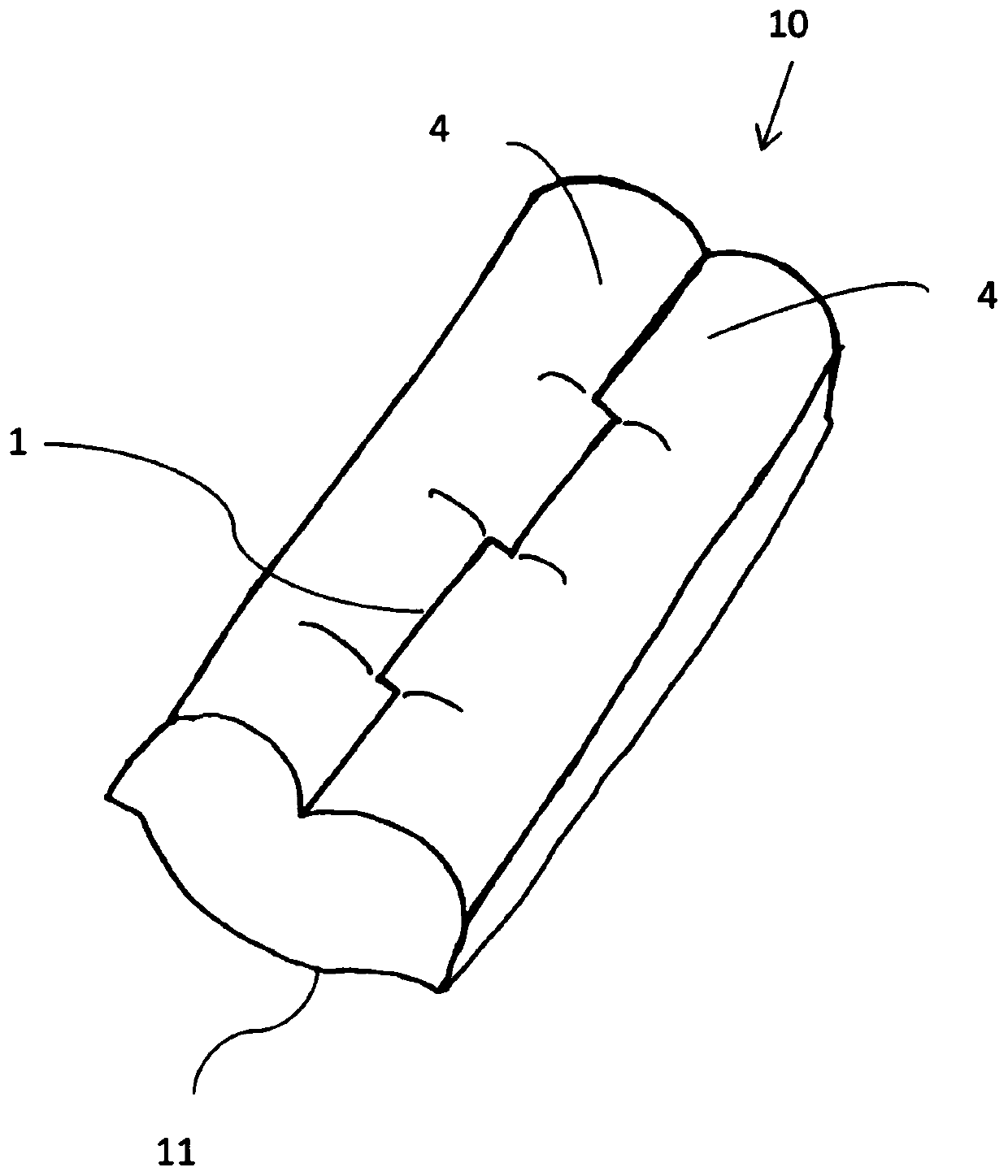
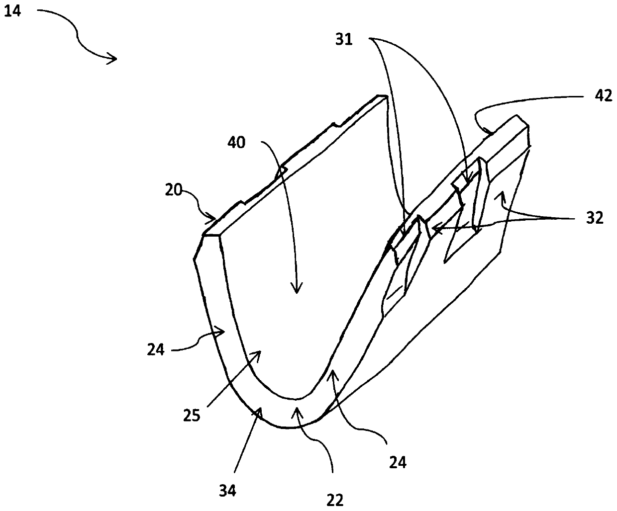
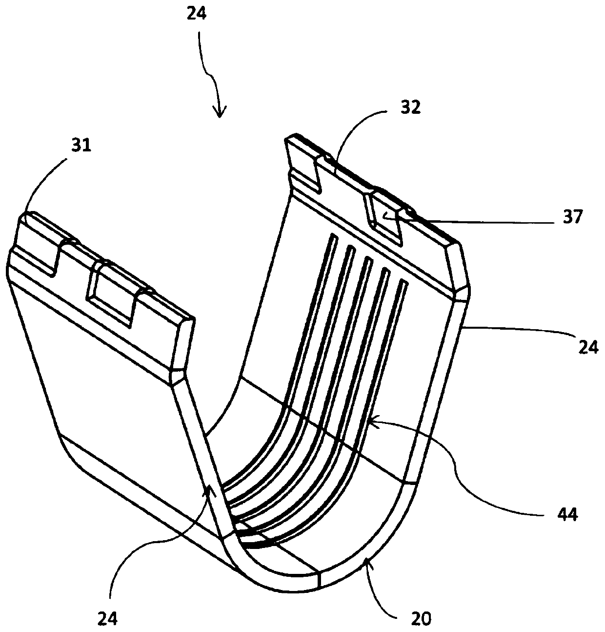
[0041] A crimp for connecting wires is provided, comprising at least one crimp barrel, wherein the crimp barrel includes at least one base and at least two opposing side walls extending from the base, wherein the side walls are adapted to bend around the wire such that The ends of the opposing side walls are joined to each other along a staggered seam.

[0042] This makes it possible to improve the locking of the seam against axial deformation of the sides and to produce additional snapping of the seam due to the axial elongation of the crimp that occurs in compression during crimp forming.

[0043] More specific examples of the present disclosure are described below. Note, however, that a detailed description may be o...


PUM


Abstract

The invention relates to a crimp for connecting wires. The crimp comprises a crimp barrel having a base and a pair of opposing side walls extending from the base. Each of the side walls is adapted tobend around a plurality of wires disposed in the crimp barrel and a pair of ends of the side walls engage with one another along a staggered seam.

Description

technical field [0001] The present disclosure relates to a crimp with increased robustness and thinner blank material. Background technique [0002] In electronics and electrical engineering, a large number of electromechanical connections are known for transmitting current, voltage and / or electrical signals at the maximum possible current, voltage and frequency ranges and / or data rates. This connection must ensure, where applicable, temporarily or permanently after a relatively long period of time, the correct transmission of mechanical contacts, electrical power, electrical signals and / or data. Accordingly, a large number of specially configured electromechanical contacts, in particular crimp contacts, are known. [0003] Crimp connections are solderless connections. Crimp connections are preferred over normal clamping of the terminal to the end of the wire. The shape of the crimp and the amount of pressure applied must be correct in order to obtain the desired connec...

Claims


Application Information

Patent Timeline
IPC IPC(8): H01R4/18
CPCH01R4/184H01R4/188F16B2/20H01R4/18H01R4/2495H01R43/058
Inventor U.布卢梅尔M.萨拉瓦纳库玛
Owner TE CONNECTIVITY INDIA
Why Eureka
Try Eureka