Supercharge Your Innovation With Domain-Expert AI Agents!

Photomask conveying device

一种输送设备、光罩的技术,应用在输送机物件、运输和包装、电气元件等方向,能够解决芯片输送盒无法再提供芯片输送、成本浪费、占用空间等问题

Active Publication Date: 2019-07-26
WINBOND ELECTRONICS CORP
View PDF5 Cites 0 Cited by
  • Summary
  • Abstract
  • Description
  • Claims
  • Application Information

AI Technical Summary

Problems solved by technology

However, the known method increases additional costs, and the modified chip transport box can no longer provide the function of chip transport, thus increasing the number of transport boxes in the factory, which not only takes up space, but also causes waste of cost

Method used


Image

  • Photomask conveying device
  • Photomask conveying device
  • Photomask conveying device

Examples


Embodiment Construction

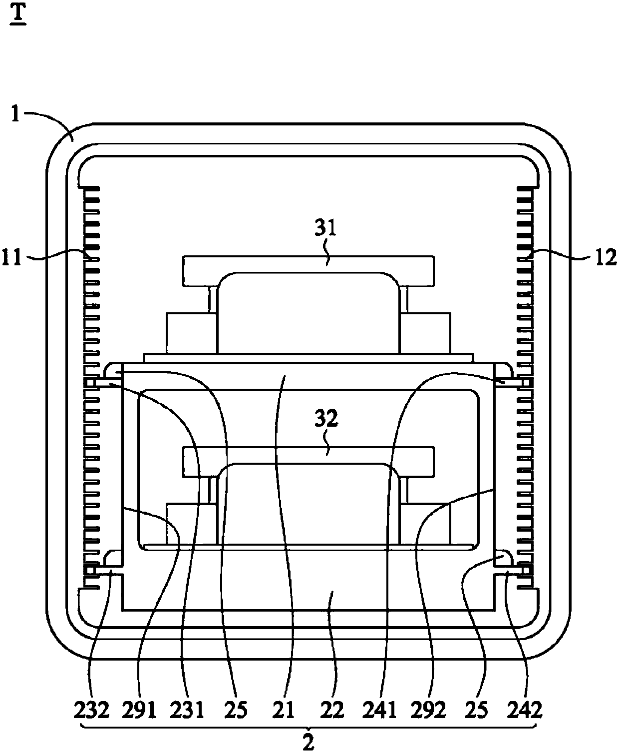
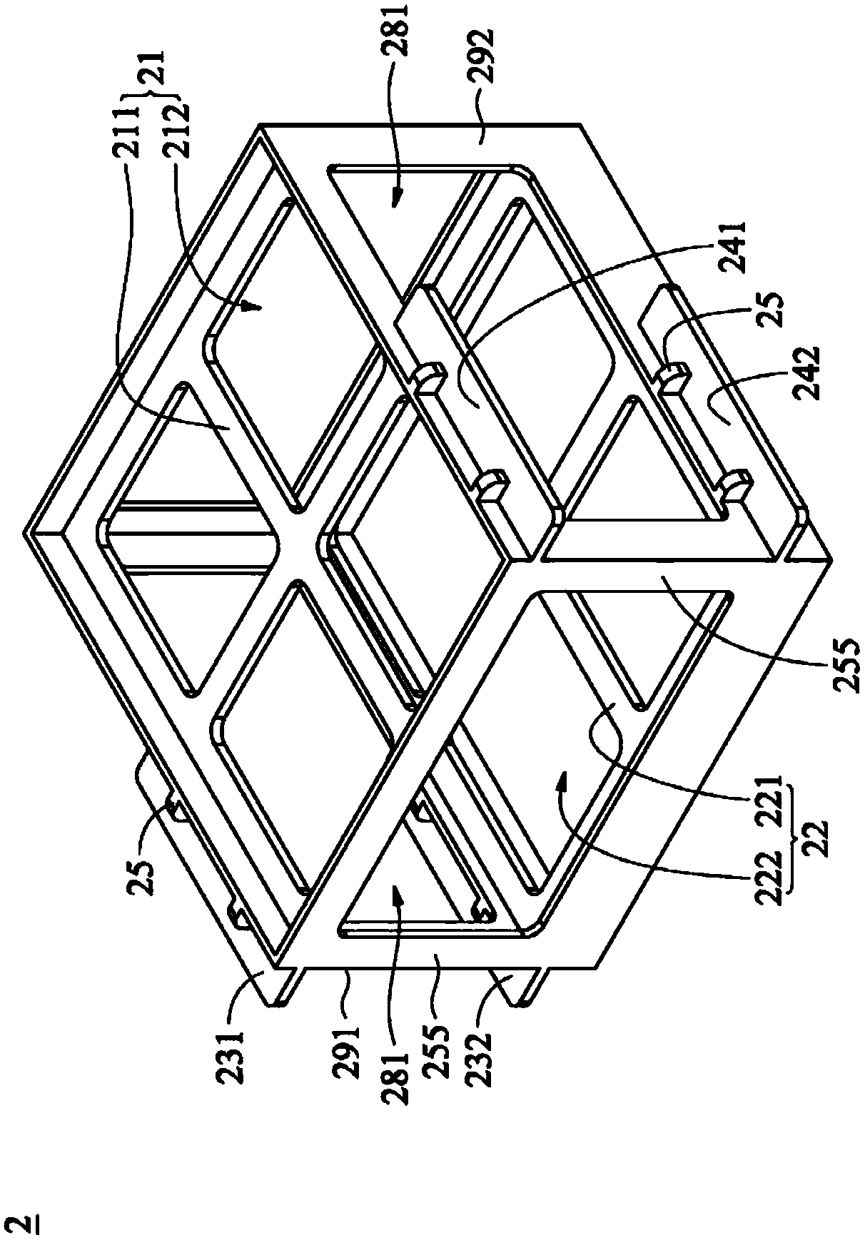
[0046] refer to figure 1 , which shows a reticle transfer device T according to an embodiment of the present invention, including a die transfer pod 1 , a support frame 2 , a first reticle pod 31 and a second reticle pod 32 . The chip delivery box 1 includes a plurality of first positioning grooves 11 and a plurality of second positioning grooves 12, the first positioning grooves 11 are opposite to the second positioning grooves 12, the first positioning grooves 11 and the second positioning grooves The positioning groove 12 is suitable for limiting a plurality of chips (not shown). The supporting frame 2 is arranged in the chip delivery box 1, and includes a first carrying unit 21, a second carrying unit 22, a first wing 231 and a second wing 241, and the first carrying unit 21 is stacked on the second On the second carrying unit 22 . The first wing 231 is disposed on a first side 291 of the support frame 2 , the second wing 241 is disposed on a second side 292 of the suppo...


PUM


Abstract

The invention provides a photomask conveying device. The photomask conveying device comprises a chip conveying box, a supporting frame, a first photomask box and a second photomask box. The chip conveying box comprises a plurality of first positioning grooves and a plurality of second positioning grooves. The supporting frame is arranged in the chip conveying box and comprises a first bearing unit, a second bearing unit, a first fin and a second fin, wherein the first bearing unit is stacked on the second bearing unit, the first fin is arranged on the first side of the supporting frame, and the second fin is arranged on the second side of the supporting frame; and the first fin is inserted into one of the first positioning grooves, and the second fin is inserted into one of the second positioning grooves. According to the photomask conveying device, a plurality of photomask boxes can be conveyed by adopting the chip conveying box. The chip conveying box can be directly combined with the supporting frame without additional modification.

Description

technical field [0001] The invention relates to a photomask conveying device, in particular to a photomask conveying device which uses a chip conveying box to convey a photomask pod. Background technique [0002] In the known technology, if it is desired to transport multiple photomask pods at the same time with a single chip transport box, the positioning groove structure of the chip transport box must be removed, and a specially designed metal bracket must be installed in the chip transport box for Holds the mask box. However, the known method increases additional costs, and the modified chip delivery box can no longer provide the function of chip delivery, thus increasing the number of delivery boxes in the factory, which not only takes up space, but also causes waste of cost. Contents of the invention [0003] The present invention provides a photomask delivery device for solving the problems of the known technology, which includes a chip delivery box, a support frame...

Claims


Application Information

Patent Timeline
Patent Type & Authority Applications(China)
IPC IPC(8): H01L21/673H01L21/677H01L21/68
CPCH01L21/677H01L21/673H01L21/682H01L21/67386H01L21/67383H01L21/67359H01L21/6773
Inventor 徐嘉禄苏耀南郑宸雅
Owner WINBOND ELECTRONICS CORP
Features
  • R&D
  • Intellectual Property
  • Life Sciences
  • Materials
  • Tech Scout
  • Unparalleled Data Quality
  • Higher Quality Content
  • 60% Fewer Hallucinations
Learn More