Feeding device for intensive care nursing

An intensive care and cavity technology, applied in the direction of therapeutic feeding tubes, etc., can solve the problem of not meeting the quantitative constant temperature requirements, and achieve the effect of easy disassembly and cleaning

Inactive Publication Date: 2019-08-13
THE FIRST AFFILIATED HOSPITAL OF ZHENGZHOU UNIV
View PDF0 Cites 3 Cited by
  • Summary
  • Abstract
  • Description
  • Claims
  • Application Information

AI Technical Summary

Problems solved by technology

[0004] In view of the above-mentioned technical problems, the purpose of the present invention is to provide a feeding device for intensive care n

Method used


Image

  • Feeding device for intensive care nursing
  • Feeding device for intensive care nursing
  • Feeding device for intensive care nursing

Examples


Embodiment 1

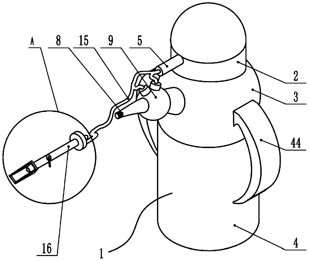
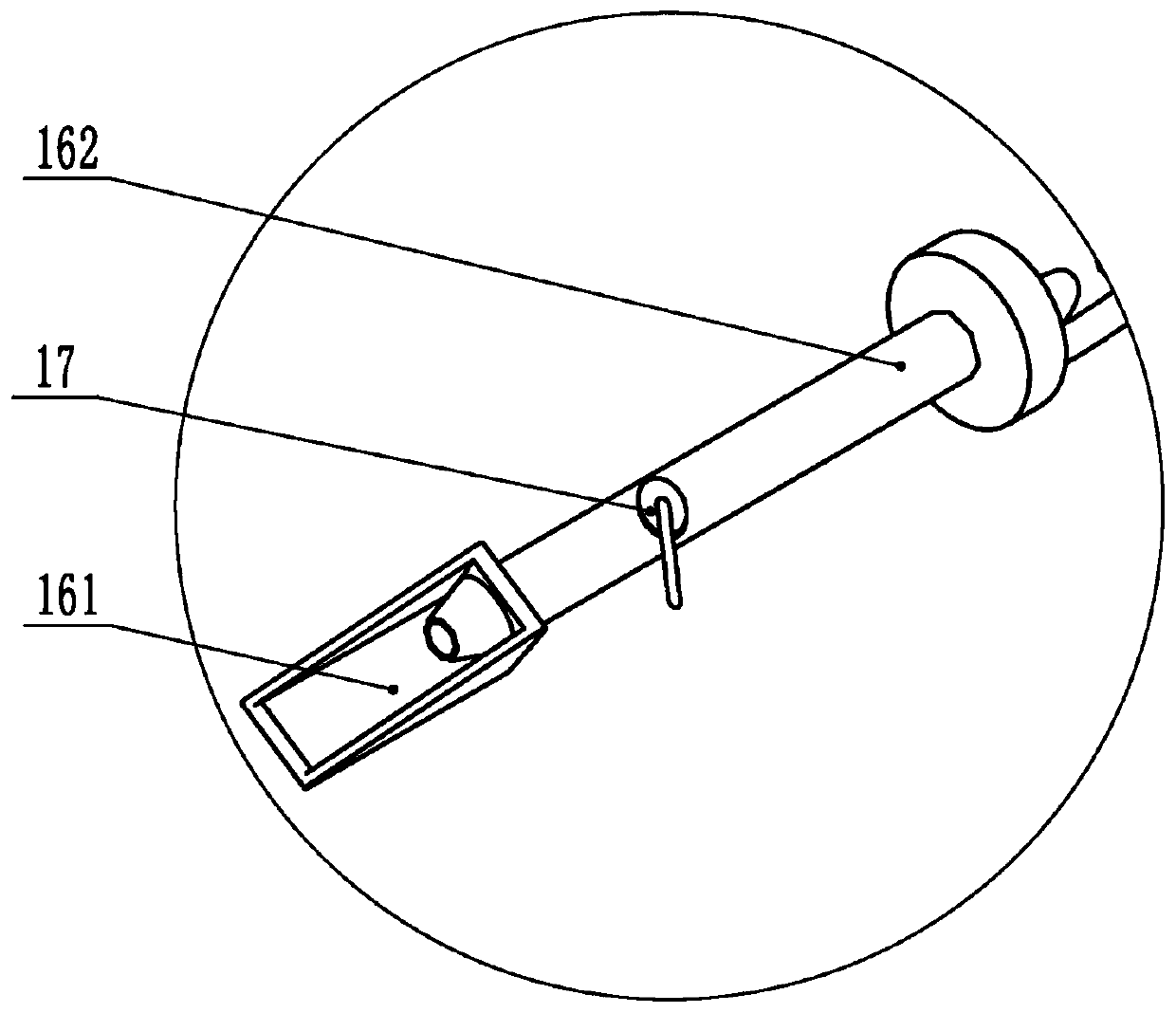
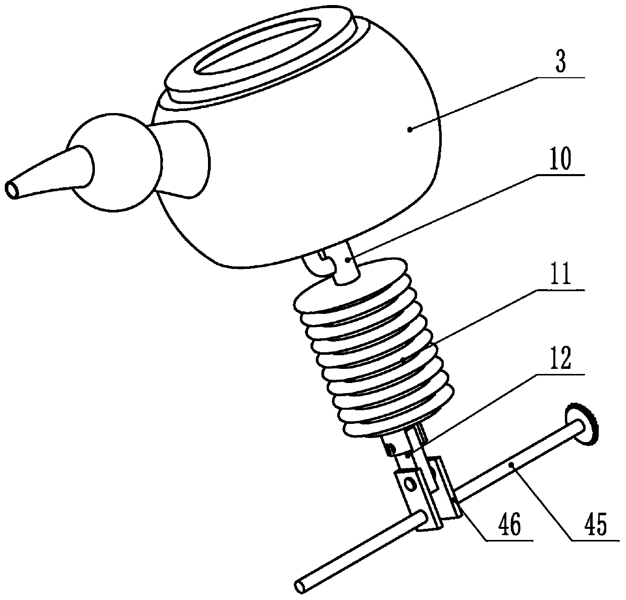
[0032] Embodiment one: by Figure 1-12 As shown, the present invention includes a housing 1, the housing 1 sequentially includes a cover 2, a first cavity 3 and a second cavity 4 from top to bottom, the cover 2 and the first cavity 3 are detachable connected, the first cavity 3 and the second cavity 4 are detachably connected, the left side of the cover 2 is fixed with a piston cylinder 5, and the cover 1 is provided with a U-shaped push rod 6 that can move left and right and Stirring device, the U-shaped push rod 6 is fixed with a piston 7, the piston 7 is in the piston cylinder 5, the first cavity 3 is fixed with a mouth 8, and the mouth 8 is provided with Spherical cavity 9, the bottom of the first cavity 3 is fixed with a first connecting pipe 10, the first connecting pipe 10 is provided with a first one-way valve, and the bottom of the first connecting pipe 10 is screwed A corrugated tube 11 is connected, and the corrugated tube 11 is provided with an insulating layer in...

Embodiment 2

[0034] Embodiment two: on the basis of above embodiment, by Figure 5 , 8 As shown, the stirring device includes a first gear 18, the first gear 18 meshes with a second gear 19, the second gear 19 is fixedly connected with a first rotating shaft 20, and the lower end of the first rotating shaft 20 is fixed The first roller 21 is connected, the side of the first roller 21 is provided with a groove 22, the pressure block 23 is slidably arranged in the groove 22, and the second rotating shaft is fixed on the first gear 18 24, the bottom end of the second rotating shaft 24 is fixed with a second roller 25, and diagonal stripes are arranged on the second roller 25; a plurality of guide columns 26 are arranged vertically in the groove 22, Each guide post 26 is fixed with an elastic member 27, and the pressure block 23 can slide on the guide post 26; the second gear 19 is provided with three, and the same first roller 21 has the same groove 22 There are four.

[0035] The first ge...

Embodiment 3

[0038] Embodiment three: on the basis of above embodiment, by Image 6 As shown, the second shaft 24 is fixed with a third gear 33, the third gear 33 is above the first gear 18, and the third gear 33 is meshed with a fourth gear 34. The gear 34 is fixedly provided with a third rotating shaft, and the third rotating shaft is fixedly provided with a cam 35; the U-shaped push rod 6 includes a first straight rod 601, a connecting rod 602 and a second straight rod 603, and the first Straight bar 601 is on the right side of cam 35.

[0039] The rotation of the first gear 18 makes the third gear 33 rotate at the same angular speed, thereby rotating the fourth gear 34 meshed with it, thereby rotating the third rotating shaft and the cam 35, and the cam 35 pushes against the first straight bar 601 to the right sports.


PUM


Abstract

The invention provides a feeding device for intensive care nursing. The problem that a quantitative constant-temperature requirement cannot be met during feeding of a critical patient is solved. The feeding device comprises a shell, a U-shaped push rod capable of moving left and right and a stirring device are arranged in the shell, the U-shaped push rod can perform quantitative food pushing, a corrugated pipe food pushing device is further arranged in the shell, and a heat preservation layer is arranged outside the corrugated pipe; the U-shaped push rod is connected with a piston cylinder, the piston cylinder is communicated with a four-way pipe, the four-way pipe is communicated with a feeding spoon, and a control valve is arranged on the feeding spoon. The device can shorten the feedingtime of the patient, heat preservation and quantification during feeding can be achieved, the living quality of the patient is improved, the workload of nursing personnel is reduced, and the feedingdevice is convenient to dismount and clean.

Description

technical field [0001] The invention belongs to the technical field of medical nursing devices, in particular to a feeding device for intensive care nursing. Background technique [0002] Patients who are severely ill or bedridden for a long time and cannot take care of themselves need to be fed by medical staff to absorb nutrients, ensure the normal physiological needs of patients, and enhance body resistance. According to the patient's condition, feeding can be taken in a sitting position, a semi-recumbent position, or lying on the healthy side. Continue to maintain the position for half an hour after eating to avoid food reflux; when eating, the amount of food per mouthful should be strictly controlled, and each tablespoon should not exceed 4ml, and the food temperature should be kept at 38-43 degrees. [0003] Because most of the critically ill patients are relatively weak, they generally eat liquid food. The existing feeding container usually uses a spoon to feed the l...

Claims


Application Information

Patent Timeline
IPC IPC(8): A61J15/00
CPCA61J15/0011A61J15/0092
Inventor 白玉玲雷声远
Owner THE FIRST AFFILIATED HOSPITAL OF ZHENGZHOU UNIV
Why Eureka
Try Eureka