A bio-based fertilizer drying device

A drying device and bio-based technology, which is applied in the direction of drying solid materials, bio-organic part processing, dry goods processing, etc., can solve the problems of low efficiency and manpower consumption, and achieve the effect of improving efficiency and quality, improving efficiency, and stable operation

Active Publication Date: 2022-08-09
宿松县华图生物科技有限公司 +1
View PDF8 Cites 0 Cited by
  • Summary
  • Abstract
  • Description
  • Claims
  • Application Information

AI Technical Summary

Problems solved by technology

[0005] The purpose of the present invention is to solve the problem of labor-intensive and low efficiency in the prior art, and propose a kind of bio-based fertilizer drying device

Method used


Image

  • A bio-based fertilizer drying device
  • A bio-based fertilizer drying device
  • A bio-based fertilizer drying device

Examples


Embodiment 1

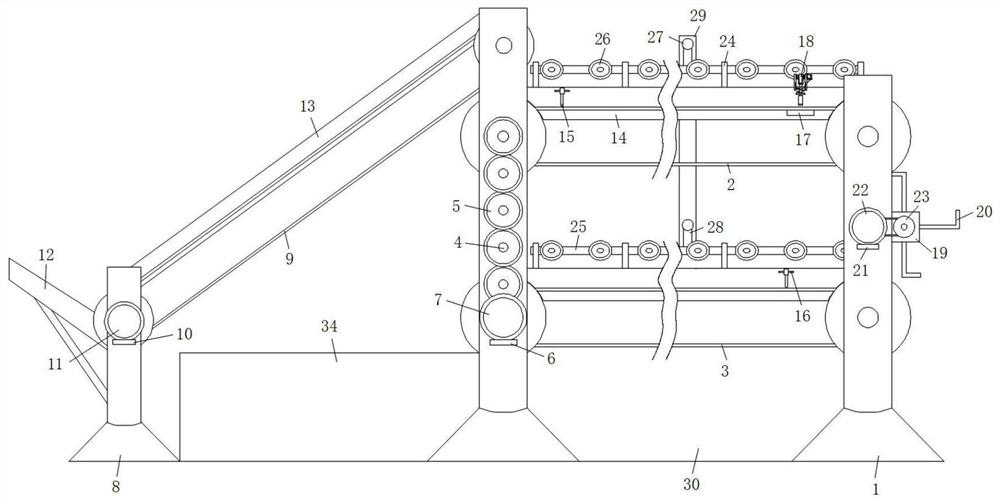
[0033] refer to Figure 1-6A biological-based fertilizer drying device, comprising a mounting seat 1, a conveyor belt 1 2 and a conveyor belt 2 3 are respectively installed on the inner sides of the upper and lower ends of the mounting seat 1 1, and the belt surfaces of the conveyor belt 1 2 and the conveyor belt 2 3 are provided with a plurality of through holes , thereby facilitating the distribution of moisture, one of the side walls of one mounting seat 1 is also rotatably connected with a transmission rod 4, the transmission rod 4 wall, the input end of the conveyor belt 2 and the input end of the conveyor belt 2 are all fixed with a transmission wheel 5 by keys, And the two adjacent transmission wheels 5 are meshed with each other, and the lower side of the transmission wheel 5 is also provided with a horizontal plate 1 6, the top surface of the horizontal plate 1 6 is fixed with a servo motor 1 7 through screws, and the output of the servo motor 1 7 is fixed. The end is...

Embodiment 2

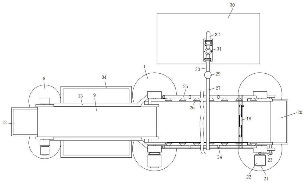
[0036] like figure 1 and 2 As shown, this embodiment is basically the same as Embodiment 1, preferably, the deodorizing mechanism includes an installation sleeve 24, and a suction branch pipe 25 is fixedly connected between the installation sleeves 24 in the same group, and the suction branch pipe 25 is close to the conveyor belt one 2 and the conveyor belt A suction funnel 26 is installed on one side of the center of the 23, and an air duct 27 is provided on the upper side of the middle of the two suction pipes 25 at the upper and lower ends. The rear side of the air duct 27 is also provided with a suction manifold 29, and the rear end of the air duct 27 is connected to the suction manifold 29 in a through connection. The rear side of the suction manifold 29 is provided with a gas purifier 30. An air pump 31 is fixedly connected, and the output end of the air pump 31 is connected to the input end of the gas purifier 30 throughly.

[0037] There are a plurality of installati...

Embodiment 3

[0040] like figure 2 As shown, this embodiment is basically the same as Embodiment 1. Preferably, four mounting bases 1 are provided and are fixed on the working surface in a rectangular shape, and two mounting bases 8 are provided and symmetrically distributed on the working surface. Front and rear position.

[0041] In this embodiment, there are four mounting seats 1 and two mounting seats 8 , so that the conveying belts 1 2 , the second conveying belts 3 , the conveying belts 1 2 and the second conveying belts 3 are conveyed more smoothly.


PUM


Abstract

The invention discloses a drying device for bio-based fertilizers, comprising a first installation seat, a conveyor belt 1 and a conveyor belt 2 are respectively installed on the inner sides of the upper and lower ends of the installation seat 1, wherein a side wall of one of the installation seats is also rotatably connected with a transmission rod, and the transmission rod The wall and the input ends of the first and second conveyor belts are fixed with transmission wheels through keys, and two adjacent transmission wheels are engaged with each other. The first surface of the servo motor is fixedly connected with the screw, and the output end of the first servo motor is fixedly connected with the input end of the second conveyor belt. The present invention has reasonable design and stable operation of the device. The three-dimensional drying method is adopted to make the feces fully contact with the sun, and during drying, the feces can be turned over and the smell can be removed, which well ensures the drying efficiency of the feces and improves the surrounding environment during drying. Air.

Description

technical field [0001] The invention relates to the technical field of auxiliary equipment for the production of bio-based fertilizers, in particular to a drying device for bio-based fertilizers. Background technique [0002] Bio-organic fertilizers are organic solid wastes, including organic waste, straw, human, livestock and poultry manure, cakes, agricultural and sideline products and solid wastes from food processing. Transfer, which requires the use of drying devices. [0003] After retrieval, the patent of application number 201921566100.5 discloses a drying equipment for biological fertilizer raw materials, including a support plate, the support plate includes a horizontally established bottom plate and a side plate fixedly connected to both sides, and the outer surface of one side of the side plate close to the front and lower end is There is a limit hole at the upper end of the support plate, a drying slot is arranged on the outer surface of the upper end of the su...

Claims


Application Information

Patent Timeline
Patent Type & Authority Patents(China)
IPC IPC(8): F26B17/04F26B3/28F26B25/00F26B25/04B08B15/04
CPCF26B17/04F26B25/04F26B25/002F26B3/28F26B25/005B08B15/04Y02W30/40
Inventor 石水琴涂健谢位冯江华
Owner 宿松县华图生物科技有限公司
Why Eureka
Try Eureka