Eureka AIR delivers breakthrough ideas for toughest innovation challenges, trusted by R&D personnel around the world.

Special rectangular punching mechanism and process

A rectangular, special technology, applied in high-precision cold stamping and machining fields, to achieve the effect of saving manufacturing cycle and saving mold structure

Inactive Publication Date: 2019-08-23
无锡有为精密模具有限公司
View PDF1 Cites 0 Cited by
  • Summary
  • Abstract
  • Description
  • Claims
  • Application Information

AI Technical Summary

Problems solved by technology

However, it cannot meet the requirements for special-shaped punching and edge-lapping.

Method used


Image

  • Special rectangular punching mechanism and process
  • Special rectangular punching mechanism and process
  • Special rectangular punching mechanism and process

Examples


Embodiment Construction

[0042] The utility model will be described in detail below in conjunction with the accompanying drawings. The description in this part is only exemplary and explanatory, and should not have any limiting effect on the protection scope of the present invention.

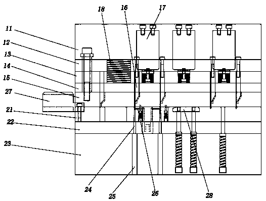
[0043] The present invention provides a special rectangular punching mechanism, which includes an upper mold assembly and a lower mold assembly, and the lower mold assembly is vertically directly below the upper mold assembly;

[0044] It is characterized in that,

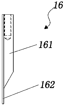
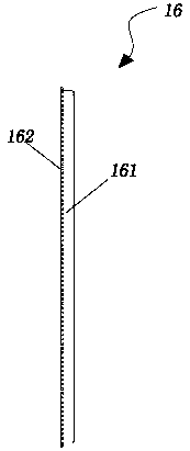
[0045] The upper mold assembly includes an upper mold base 11, an upper backing plate 12, an upper splint 13, a discharge backing plate 14, a discharge plate 15, a punch 16, a nitrogen pressure pump 17, and a nitrogen spring 18;

[0046] The lower mold assembly includes a lower template 21, a lower backing plate 22, a lower mold base 23, a die 24, a lower ejector pin 25, a blanking device 26, a material guide block 27, and a floating block 28;

[0047] The ...


PUM


Abstract

The invention aims to better improve the process flow of punching new products, meet the requirements of customrs for punching products, shorten the period, reduce the cost and improve the efficiency.The invention provides a special rectangular punching mechanism which comprises an upper die assembly and a lower die assembly, wherein the lower die assembly is right under the upper die assembly; the upper die assembly comprises an upper die seat 11, an upper backing plate 12, an upper clamping plate 13, a discharging backing plate 14, a discharging plate 15, a punch 16, a nitrogen pressure pump 17 and a nitrogen spring 18; the lower die assembly comprises a lower die plate 21, a lower backing plate 22, a lower die seat 23, a female die 24, a lower ejector rod 25, a blanking device 26, a guide block 27 and a floating block 28; the punch 16 comprises a punch seat 161 and a punch top 162; the punch seat 161 extends downwards out of the punch top 162; the punch seat 161 is wider than the punch top 162; and the angle between the wedge surface at the junction of the punch top 162 and the punch seat 161 and the punch top 162 is 30 degrees.

Description

technical field [0001] The invention relates to the field of mechanical processing, in particular to the field of high-precision cold stamping. Background technique [0002] High quality, short delivery time, and low cost are the eternal requirements of customers for product parts. With the progress of the times, the information industry and electronic components are also developing and updating rapidly, and the requirements for the stamping process are getting higher and higher. The ordinary stamping process in the past can no longer meet the requirements of new products. The previous punching process can be completed with wire cutting punch, punching die and ordinary grinding. However, it cannot meet the requirements for special-shaped punching and edge-lapping. [0003] A Chinese invention patent has been published, publication number: CN105363816B, patent name: a micro-hole stamping forming process, application date: 20151204, which discloses a technology in the field ...

Claims


Application Information

Patent Timeline
Patent Type & Authority Applications(China)
IPC IPC(8): B21D28/24B21D28/34
CPCB21D28/24B21D28/34
Inventor 王军
Owner 无锡有为精密模具有限公司
Why Eureka
Eureka Blog
Learn More