Heat control device for a combustion furnace

A heat control and combustion furnace technology, applied in the control of combustion, combustion methods, combustion equipment, etc., can solve problems such as heat loss, and achieve the effects of good reflection and heat resistance, convenient installation and disassembly, and efficient heat utilization.

Active Publication Date: 2021-08-27
周应进
View PDF9 Cites 0 Cited by
  • Summary
  • Abstract
  • Description
  • Claims
  • Application Information

AI Technical Summary

Problems solved by technology

[0004] The purpose of the present invention is to overcome the deficiencies of the prior art, adapt to the actual needs, and provide a heat control device for a combustion furnace to solve the problem that the heat in the existing combustion furnace will be lost with the drive of the blower and the induced draft fan

Method used


Image

  • Heat control device for a combustion furnace
  • Heat control device for a combustion furnace
  • Heat control device for a combustion furnace

Examples


Embodiment Construction

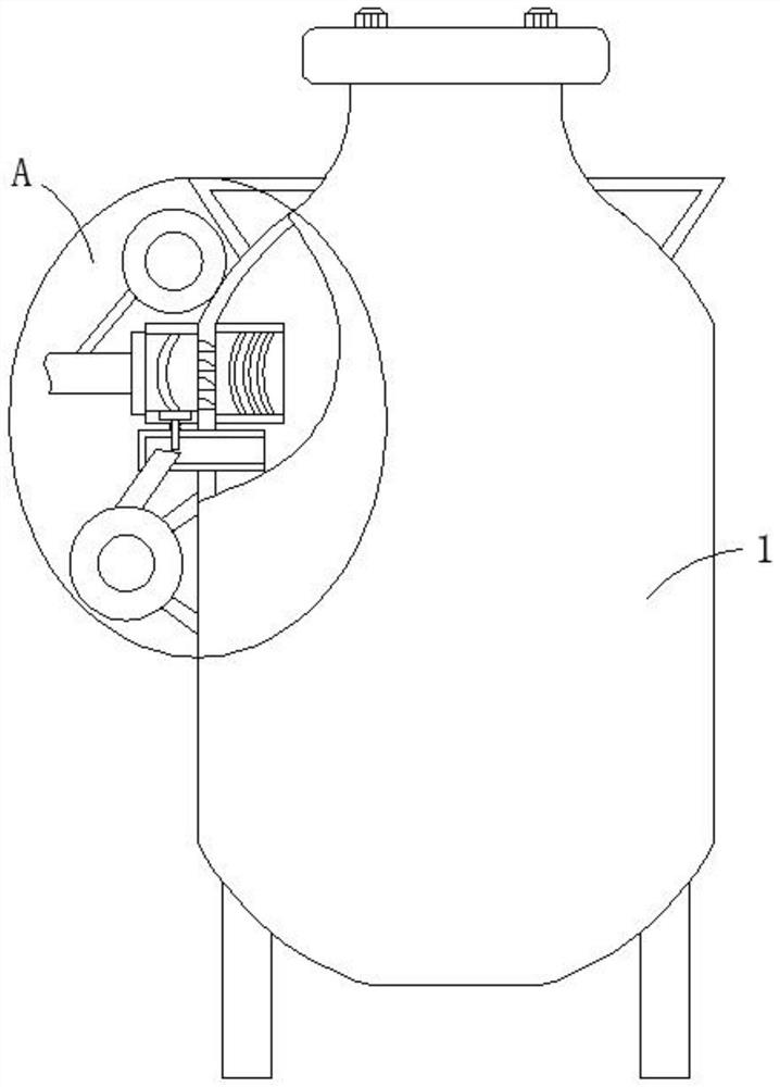
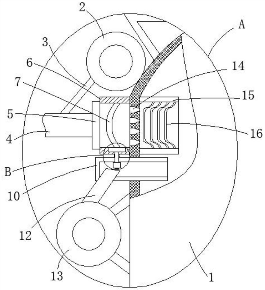
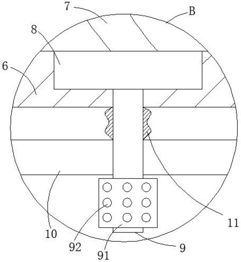
[0028] Attached below Figure 1-6 The present invention is further described with embodiment:

[0029] A heat control device for a combustion furnace, comprising an exhaust hole 14 and a heat-resistant plate 16, the exhaust hole 14 is set on the side plate of the combustion furnace 1, the heat-resistant plate 16 is arranged in the heat-resistant tube 15, and the heat-resistant tube 15 is fixed It is arranged on the inner side plate of the combustion furnace 1, and the heat-resisting plate 16 is provided with a first heat conduction hole, and the heat-resisting plate 16 is set as a pot-shaped structure, and the number of the heat-resisting plates 16 is at least four, and the four heat-resisting plates 16 are equidistantly distributed, the heat resistance pipe 15 is matched with the exhaust hole 14, and the heat transfer tube 6 is fixedly installed outside the combustion furnace 1, and the heat transfer tube 6 is matched with the exhaust hole 14, and the heat transfer tube 6 is ...


PUM


Abstract

The invention relates to a heat control device for a combustion furnace, which aims to solve the problem that the heat in the existing combustion furnace will be lost with the drive of the blower and the induced draft fan. On the side plate of the combustion furnace, the heat resistance plate is arranged in the heat resistance tube, and the heat resistance tube is fixedly arranged on the inner side plate of the combustion furnace, and the heat resistance plate is provided with a first heat conduction hole; in the present invention, a pot-shaped resistance is designed The heat plate is combined with several heat-resistant plates, which can achieve the effect of convenient installation and disassembly. At the same time, there are multiple exhaust holes on the combustion furnace, and the front diameter of the exhaust hole is small, and the reverse diameter is large. And the caliber is tapered. The purpose of this setting is that the front caliber is small, which can play a better role in reflecting light and heat, so as to avoid the loss of high-temperature heat, so as to achieve a better use of heat. At the same time, the heat-resistant plate It has the functions of anti-corrosion, high temperature resistance and reflective heat.

Description

technical field [0001] The invention relates to the technical field of heat recovery equipment, in particular to a heat control device for a combustion furnace. Background technique [0002] In coal-burning and biomass-burning enterprises, it is often necessary to use high temperature to work during the production process, but in the operation of the combustion furnace, due to the work of the blower and induced draft fan, the high temperature will be eliminated with the work of the blower and induced draft fan Air flows away, thereby causing heat loss, resulting in an increase in production costs. In order to solve the above problems, the present invention proposes a heat control device for a combustion furnace. Contents of the invention [0003] (1) Technical problems to be solved [0004] The purpose of the present invention is to overcome the deficiencies of the prior art, meet the actual needs, and provide a heat control device for a combustion furnace to solve the pr...

Claims


Application Information

Patent Timeline
Patent Type & Authority Patents(China)
IPC IPC(8): F23B80/00F23L5/02F23N5/26F23L3/00
CPCF23B80/00F23L3/00F23L5/02F23N5/26
Inventor 周应进
Owner 周应进
Why Eureka
Try Eureka