Injection valve

A jet valve and gap technology, applied in the field of jet valves, can solve problems such as short service life of metering needles

Inactive Publication Date: 2019-09-20
MARCO SYSTEMANALYSE UND ENTWICKLUNG GMBH
View PDF6 Cites 0 Cited by
  • Summary
  • Abstract
  • Description
  • Claims
  • Application Information

AI Technical Summary

Problems solved by technology

In fact, this shape makes the service life of the metering needle very short

Method used


Image

  • Injection valve
  • Injection valve

Examples


Embodiment Construction

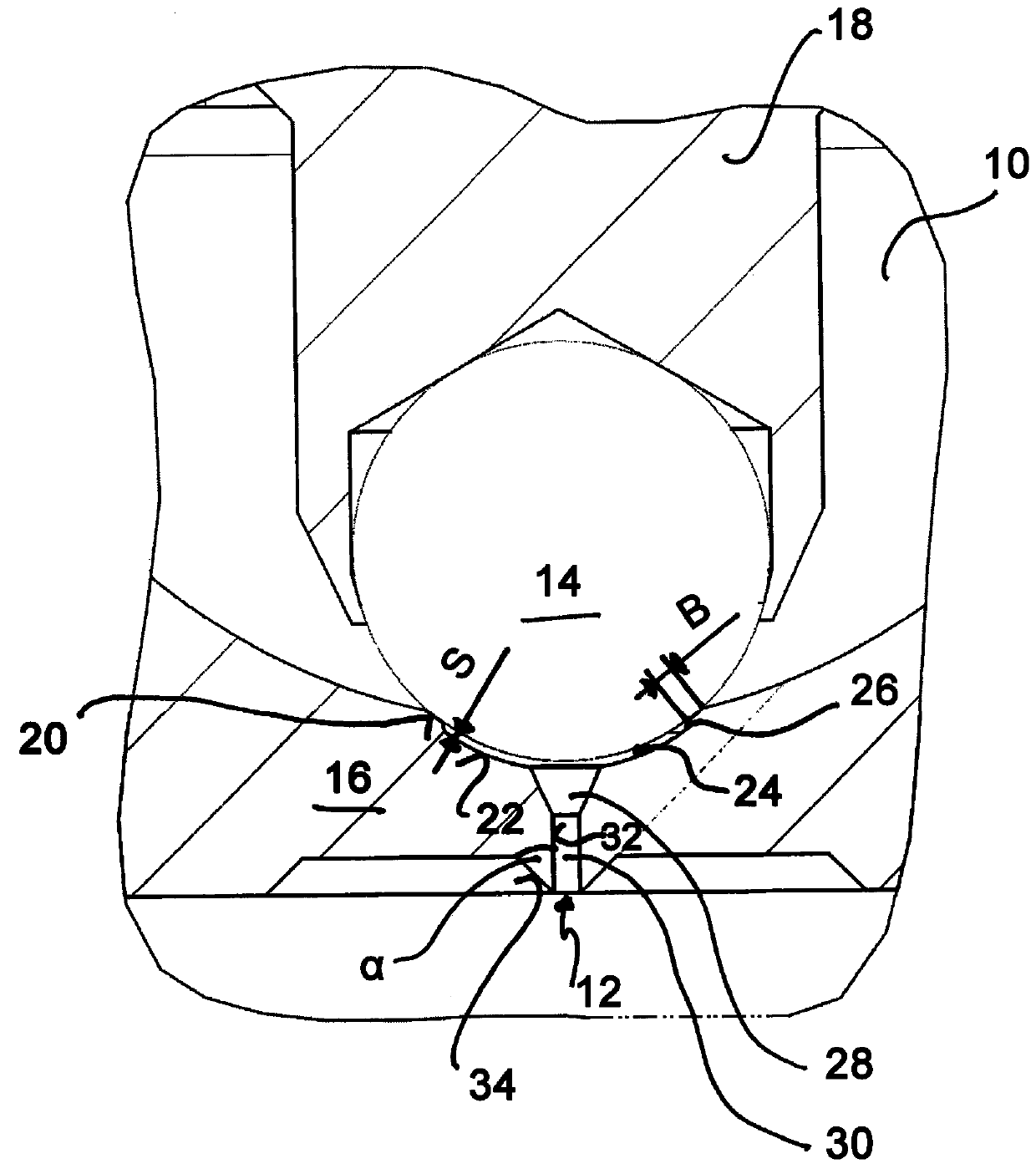
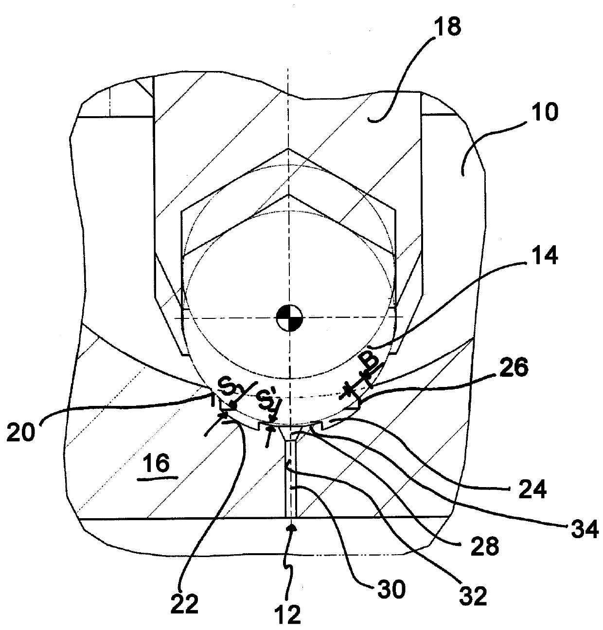
[0025] figure 1 The injection valve shown only partially in FIG. 2 has a medium channel 10 which leads to an outlet opening 12 and which can be closed by a sealing element 14 which can be arranged against a sealing seat 16 . The sealing element 14 in the illustrated embodiment has a spherical shape, which is fixed to one end of the valve needle 18 . Here, the valve needle is arranged in a known manner on the sealing seat by a valve drive having a sufficiently high number of cycles against the force of the spring.

[0026] A sealing surface 20 formed on the valve seat 16 serves for sealing between the sealing element 14 and the valve seat 16 . Said sealing face 20 is formed in the form of a sealing chamfer and has the shape of an annular strip of width B as part of the spherical surface of the illustrated embodiment.

[0027] The sealing seat 16 also has a surface contour 22 behind the sealing surface 20 in the direction of the outlet opening 12 , which is spaced apart from t...


PUM


Abstract

An injection valve has a media channel leading to an outlet, which media channel can be closed by a sealing element, which can be arranged against a sealing seat. The sealing seat has a sealing surface in the form of an annular strip. The service life of the injection valve is long, and the injection valve is suitable for metering a very small amount.

Description

technical field [0001] The present application relates to an injection valve for contactless metering of a quantity of a medium. Background technique [0002] In the production of electronic components and devices such as smartphones and tablets, a large number of production steps require the gluing process. Injection valves are often used for this purpose because, on the one hand, they enable the non-contact application of adhesive (or other media) and, on the other hand, they also enable a very high measurement frequency. As the components of electronic devices become increasingly miniaturized, smaller drops of adhesive and narrower bonding gaps are required. Furthermore, the metering quantity dispensed per shot also depends on the shape of the sealing seat of the metering valve. [0003] The shape of the seal seat usually consists of a spherical ball, a cone, a cylinder, or multiple flat surfaces, depending on manufacture. The same applies to the sealing element, typic...

Claims


Application Information

Patent Timeline
Patent Type & Authority Applications(China)
IPC IPC(8): B05C5/02B05C11/10F16K1/34F16K25/00
CPCB05C5/0233B05C11/1031F16K1/34F16K25/00
Inventor 马丁·路透
Owner MARCO SYSTEMANALYSE UND ENTWICKLUNG GMBH
Why Eureka
Try Eureka