
Reinforcing steel bar connector of moving casing pipe and full-grouting sleeve

A steel connector and full grouting technology, which is applied to structural elements, building components, building reinforcements, etc., can solve the problems of strong construction concealment, deformation, and difficult quality control, so as to avoid inconvenience and construction hidden dangers. wide range of effects

Inactive Publication Date: 2019-09-20
SHANGHAI YIPINLILIAN CONSTR TECH CO LTD
View PDF0 Cites 1 Cited by
  • Summary
  • Abstract
  • Description
  • Claims
  • Application Information

AI Technical Summary

Problems solved by technology

[0002]The use of prefabricated buildings in the field of current engineering construction is becoming more and more common. In the prefabricated building structure, the connection of steel bars is the most widely used method of grouting sleeve connection. However, since the grout in the grouting sleeve needs to be poured and pressed in through a thinner pipe in the later stage, due to the narrow space in the grouting sleeve, it is very easy to cause the grout to be not dense during the grouting and pressing process due to factors such as incomplete air discharge. Moreover, there is currently no effective and reliable detection method for non-destructive testing of grouting compactness. At the same time, if it is not dense, it is difficult to use simple grouting and other methods to repair it. Therefore, the traditional grouting sleeve connection method has a strong construction concealment. , Quality is difficult to control, lack of reliable detection methods and inspection standards and other shortcomings
[0003]Another construction method of grouting sleeve connection is to pour the slurry reinforcement into the sleeve before connecting, and then the pre-embedded reinforcement on the other side of the prefabricated component The connection can be realized by inserting into the sleeve filled with grout. Although this method can avoid the inconsistency of the grout, since the steel bar inserted into the sleeve needs to protrude from the surface of the prefabricated component, it will greatly affect the transportation and installation of the prefabricated component. Inconvenient, and the protruding steel bars on the prefabricated components are easily deformed due to contact and other reasons during transportation and installation, which will cause hidden dangers to the later construction and project quality

Method used


Image

  • Reinforcing steel bar connector of moving casing pipe and full-grouting sleeve
  • Reinforcing steel bar connector of moving casing pipe and full-grouting sleeve
  • Reinforcing steel bar connector of moving casing pipe and full-grouting sleeve

Examples


Embodiment 1

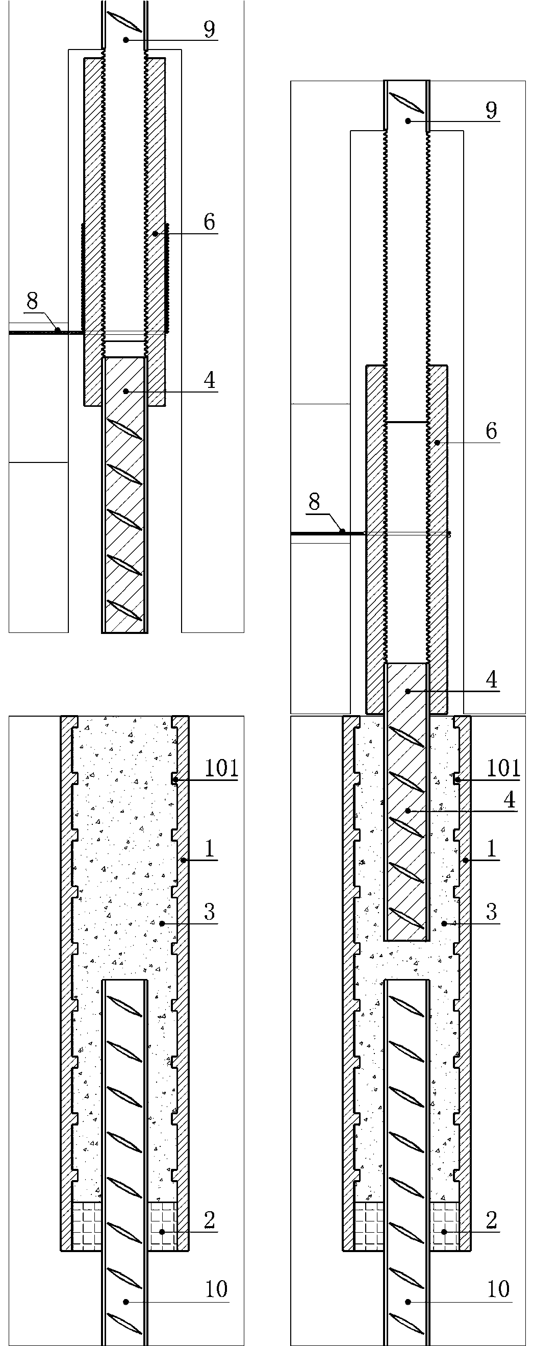
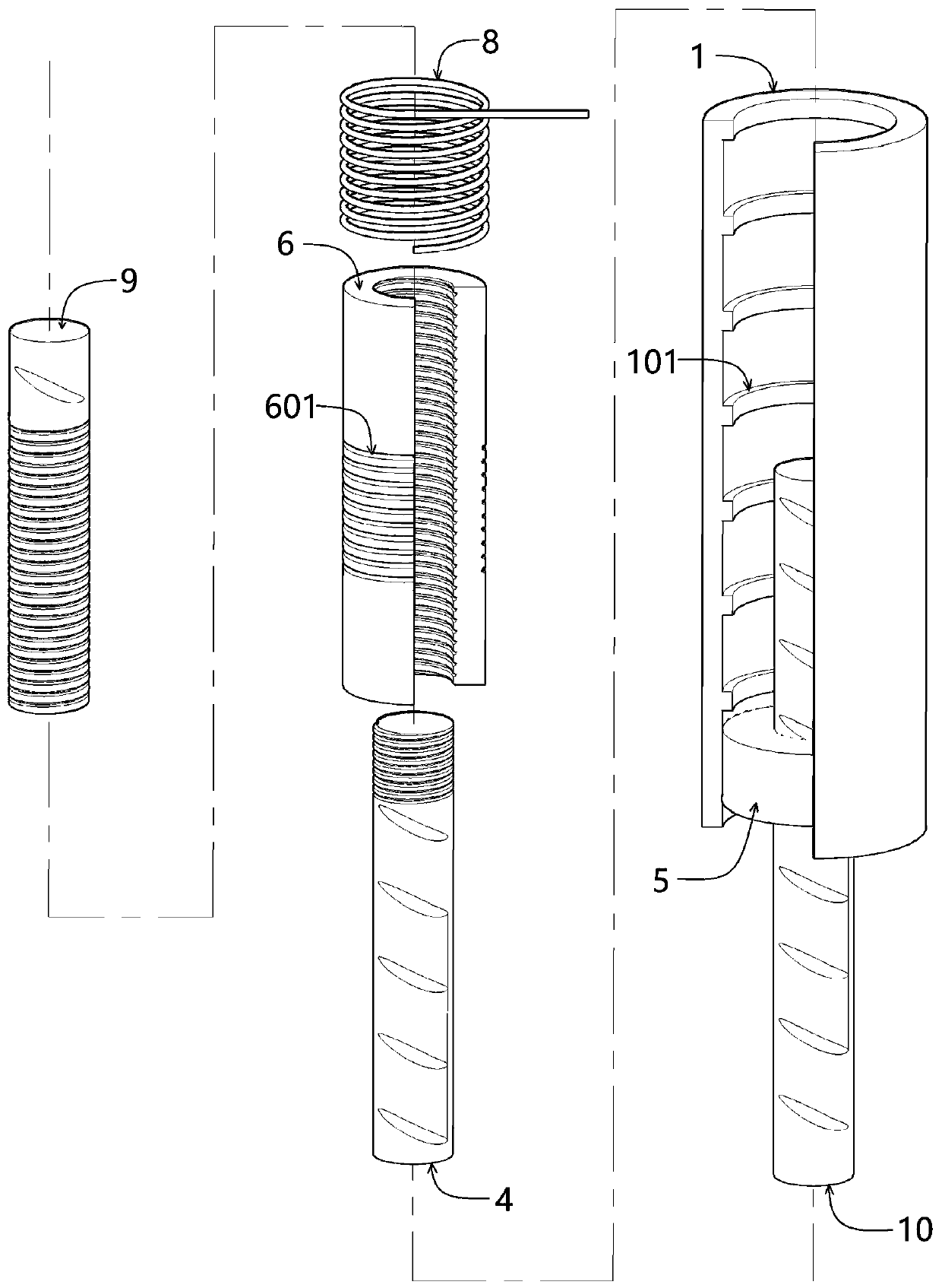
[0020] Such as figure 1 and figure 2 As shown, a specific embodiment of the present invention, connecting steel bar one 9 and steel bar two 10, is characterized in that: it comprises full grouting sleeve 1, sealing ring 2, cement-based slurry 3, connecting rod 4, moving sleeve 6 and Steel wire rope 8; connecting rod 4 and moving sleeve 6 form a connector male joint, moving sleeve 6 is connected with steel bar 9 by a threaded pair, and moving sleeve 6 is connected with connecting rod 4 by a threaded pair; full grouting sleeve 1 and sealing The ring 2 forms the female joint of the connector, the steel bar 10 extends into the full grouting sleeve 1, and the sealing ring 2 is used to seal between the steel bar 2 10 and the full grouting sleeve 1.

[0021] The inner wall of the full grouting sleeve 1 is provided with a circumferentially protruding shear key 101, the full grouting sleeve 1 is filled with cement-based slurry 3, the outer side of the moving sleeve 6 is provided with...

Embodiment 2

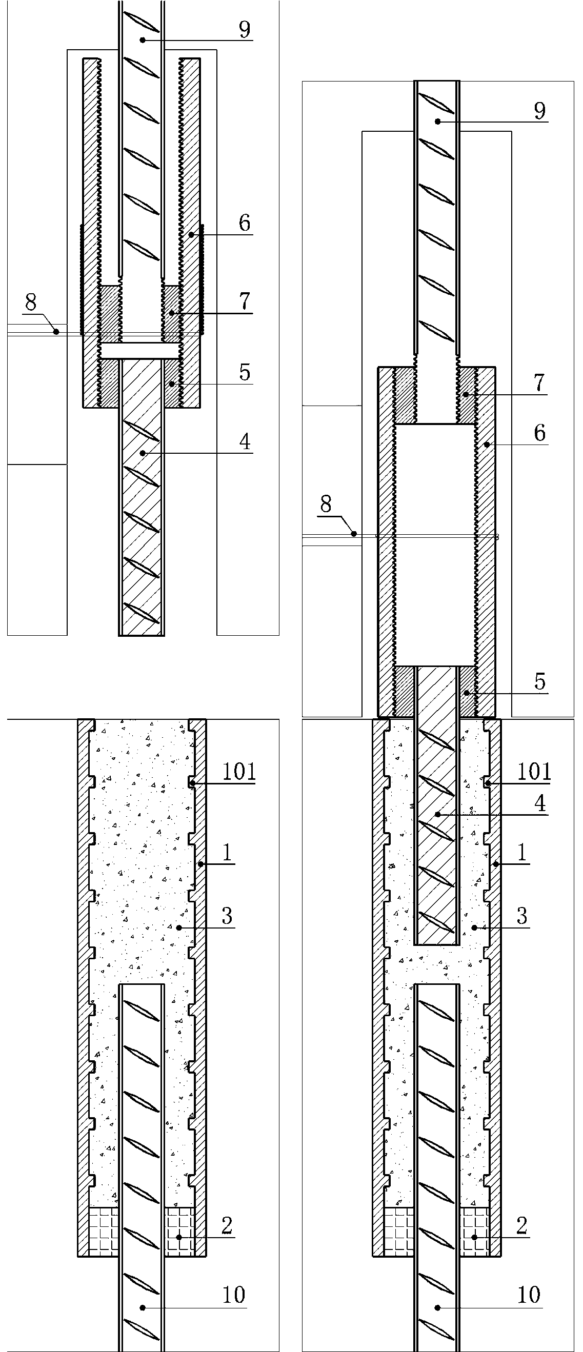
[0023] Such as image 3 and Figure 4 As shown, a specific embodiment of the present invention, connecting steel bar one 9 and steel bar two 10, is characterized in that: it includes a full grouting sleeve 1, a sealing ring 2, cement-based slurry 3, a connecting rod 4, and a first connecting nut 5 , the moving sleeve 6, the second connecting nut 7 and the steel wire rope 8; the connecting rod 4, the first connecting nut 5, the moving sleeve 6 and the second connecting nut 7 form the male joint of the connector, and the two ends of the moving sleeve 6 are respectively provided with the second One connecting nut 5 and the second connecting nut 7, the first connecting nut 5 is connected with the connecting rod 4 and the moving sleeve 6 with the internal and external thread pairs, and the second connecting nut 7 is connected with the reinforcing bar 9 and the moving sleeve 6 with the internal and external threads; The grouting sleeve 1 and the sealing ring 2 form the connector fe...


PUM


Abstract

The invention provides a reinforcing steel bar connector of a moving casing pipe and a full-grouting sleeve. The reinforcing steel bar connector of the moving casing pipe and the full-grouting sleeve connects a first reinforcing steel bar and a second reinforcing steel bar with deviations and comprises the full-grouting sleeve, a sealing ring, cement-based slurry, a connection rod, the moving casing pipe and a pulling piece; one end of the moving casing pipe is connected with the first reinforcing steel bar, and the other end of the moving casing pipe is connected with the connection rod; the second reinforcing steel bar extends into the full-grouting sleeve, and the second reinforcing steel bar and the full-grouting sleeve are sealed by the sealing ring; the cement-based slurry is poured into the full-grouting sleeve; and the pulling piece is arranged on the outer side of the moving casing pipe, after the pulling piece is pulled, the connection rod is pushed to extend out of a prefabricated member after the moving casing pipe rotates, the connection rod is inserted into the full-grouting sleeve filled with the cement-based slurry, and connection of the connector is realized. According to the reinforcing steel bar connector of the moving casing pipe and the full-grouting sleeve, the problem of uncompacted grouting in grouting sleeve connection of an assembly structure is solved, and various inconvenience and construction hidden danger caused by pre-embedded reinforcing steel bars extending out of the prefabricated member are further avoided.

Description

technical field [0001] The invention relates to the technical field of connection of steel bars, in particular to a fully grouted sleeve steel bar connector for moving sleeves. Background technique [0002] In the field of current engineering construction, the use of prefabricated buildings is becoming more and more common. The most widely used method for the connection of steel bars in prefabricated building structures is grouting sleeve connection. However, the grout in the grouting sleeve needs to pass through thinner pipes later. For grouting and pressing, due to the narrow space in the grouting sleeve, it is very easy to cause the grout to be not dense due to factors such as incomplete air discharge during the grouting and pressing process, and there is currently no effective and reliable detection method for non-destructive grouting compactness At the same time, if it is not compacted, it is difficult to use simple grouting and other methods to repair it. Therefore, th...

Claims


Application Information

Patent Timeline
Patent Type & Authority Applications(China)
IPC IPC(8): E04C5/16
CPCE04C5/165
Inventor 郭卓明
Owner SHANGHAI YIPINLILIAN CONSTR TECH CO LTD
Learn More