Chair

A technology of chairs and lifting rods, applied in the field of chairs, can solve the problems of inability to adjust the height, fail to meet the sliding function of the chair, and damage the wooden floor by the casters, so as to achieve the effect of improving the comfort of use

Pending Publication Date: 2019-09-24
陶国慧
View PDF0 Cites 0 Cited by
  • Summary
  • Abstract
  • Description
  • Claims
  • Application Information

AI Technical Summary

Problems solved by technology

[0003] At present, chairs are generally equipped with lifting rods and other structures, so that the overall height of the chair can be adjusted and the seat cushion of the chair can be rotated, but other parts, such as backrest cushions, cannot be adjusted in height, which cannot meet the needs of different customers.
Moreover, chairs usually have two types: with casters and without casters. If the customer buys a chair with casters, it cannot be used in a room with wooden floors. The casters will damage the wooden floor. Although the casters can be disassembled, the chair after removing the casters The bottom feet can also damage the wooden floor. If the customer buys a chair without casters, it cannot satisfy the sliding function of the chair

Method used


Image

  • Chair
  • Chair
  • Chair

Examples


Embodiment 1

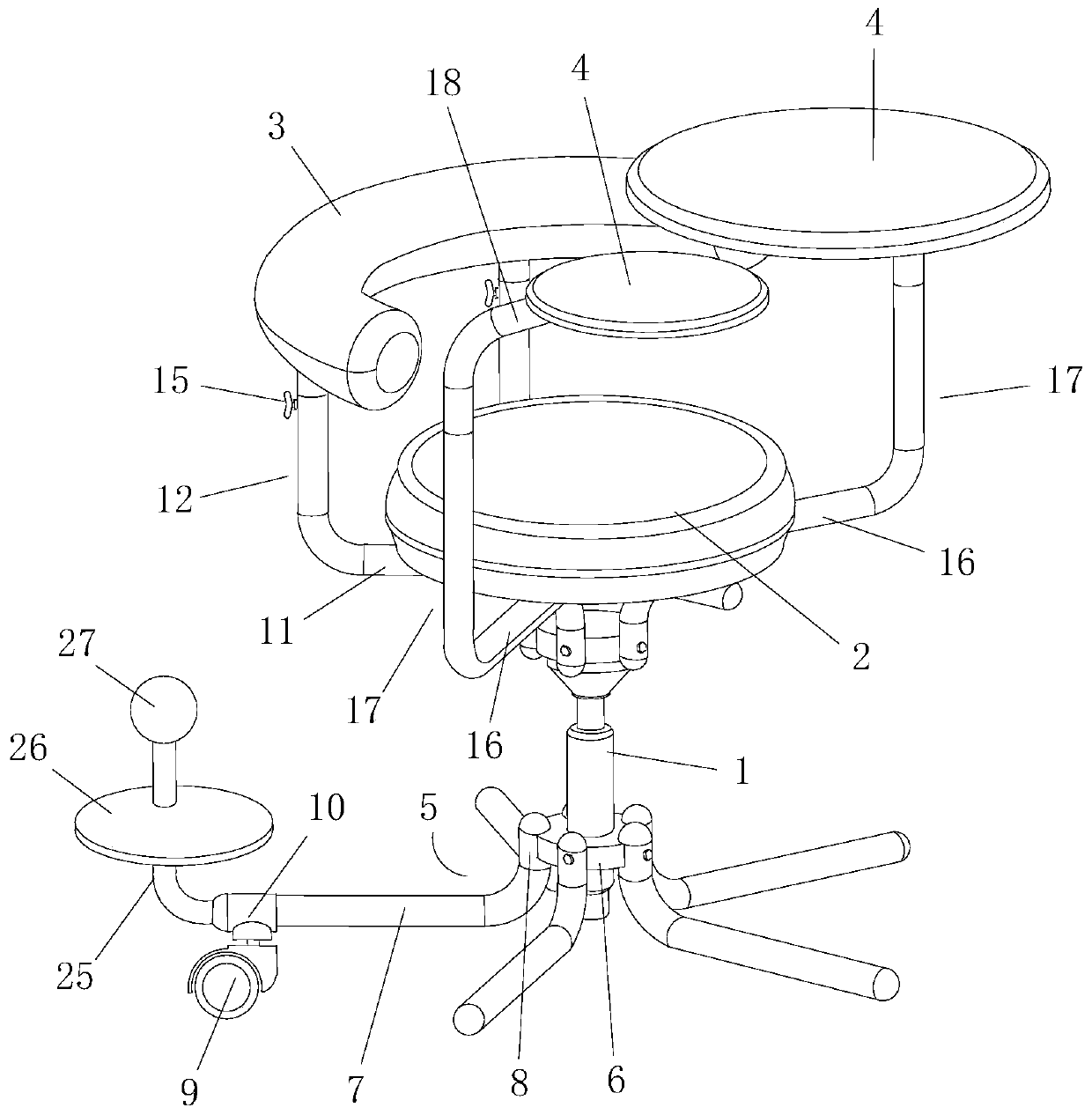
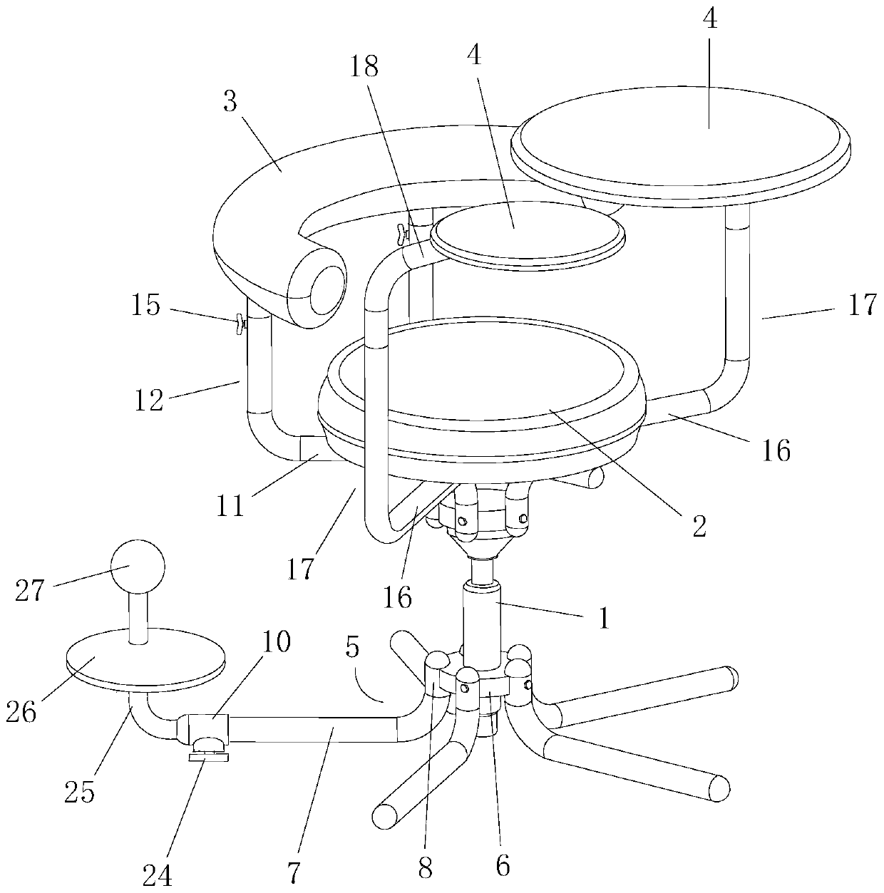
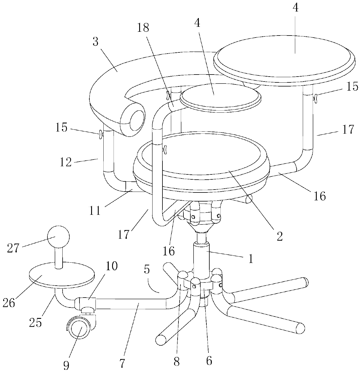
[0031] Example 1, see figure 1 , 2 , 7 and 8: a chair, comprising a lift rod 1, a seat cushion 2, a backrest pad 3, a platform 4, a foot support rod 5, a backrest support rod and a platform support rod, the upper and lower ends of the lift rod 1 are respectively A connecting seat 6 is installed, and a rotating shaft is connected between the lifting rod 1 and the connecting seat 6 at the upper end, wherein the lifting rod 1 is a pneumatic lifting rod or a hydraulic lifting rod of the prior art, and a lifting valve switch is also connected on it (the accompanying drawing). not shown), so that the connecting seat 6 at the upper end can be lifted and rotated.

[0032] specific,

[0033] There are at least three foot support rods 5, which are evenly installed on the outer circumference of the connecting seat 6 at the lower end of the lifting rod 1. The foot support rod 5 is formed by bending a pipe, and is formed with a horizontal support portion 7 and a connecting portion. 8. T...

Embodiment 2

[0037] Example 2, see image 3 , 4, 8: a chair, the difference from Embodiment 1 is that the vertical rod 12 includes an upper rod body 13 and a lower rod body 14 integrally connected with the bearing part 11, and the lower rod body 14 is provided with a shaft The upper rod body 13 is inserted into the sliding cavity and can move up and down in the sliding cavity. The upper end of the lower rod body 14 is provided with a screw hole communicating with the sliding cavity, and the screw hole is screwed with a limit bolt 15 (see Figure 8 ), tighten the limit bolt 15 to make it push the upper rod body 13, so as to fix the upper rod body 13. The backrest pad 3 is installed on the upper end of the upper rod body 13 .

[0038] The second vertical rod 17 includes a lower rod body 14 integrally connected with the supporting part 2 16 and an upper rod body 13 integrally connected with the cantilever rod 18 . The lower rod body 14 is provided with an axial sliding cavity, and the uppe...

Embodiment 3

[0039] Example 3, see Figure 5 , 6 , 9 and 10: the vertical rod 12 includes an upper rod body 13 and a lower rod body 14 integrally connected with the bearing part 11, the lower rod body 14 is provided with an axial sliding cavity, and the upper rod body 13 is inserted The lower rod body 14 and the upper rod body 13 are provided with a limiting device 19, and the limiting device 19 includes a limiting sleeve and a tightening cap 20. The limiting device The sleeve includes a base portion 21 fixedly mounted on the upper end of the lower rod body 14 and a conical limiting portion 22 sleeved on the upper rod body 13 and in clearance fit with the upper rod body 13. The conical limiting portion 22 is provided with an axial The opening groove body 23, the tapered limiting portion 22 is provided with an external thread, the tightening cap 20 is sleeved on the upper rod body 13, and the tightening cap 20 is provided with a matching tapered limiting portion 22. A tapered screw hole, ...


PUM


Abstract

The invention discloses a chair. The chair comprises a lifting rod, a seat cushion, a backrest cushion and connecting seats, the chair is characterized in that at least three bottom foot supporting rods are installed on the periphery of the connecting seat at the lower end of the lifting rod, the bottom foot supporting rods comprise horizontal supporting pars and connecting parts, and the connecting parts are fixedly connected to the periphery of the connecting seat at the lower end of the lifting rod; a backrest support rod is connected between the backrest cushion and the rear side of the connecting seat at the upper end of the lifting rod; and a platform support rod is arranged on the left side and / or the right side of the connecting seat at the upper end of the lifting rod, and a platform is arranged on the platform support rod. According to the chair, the lifting rod can adjust the overall height of the chair, the backrest support rod which can be extended and shortened is connected between the backrest cushion and the rear side of the connecting seat at the upper end of the lifting rod, the platform support rod which can be extended and shortened is further arranged, the platform for writing and placing objects is installed on the upper overhanging rod of the platform support rod, the height of the backrest cushion and the platform can be adjusted at will, using needs of different customers are met, and the comfort of use is improved.

Description

technical field [0001] The invention belongs to the technical field of clamps, and in particular relates to a chair. Background technique [0002] The chair is very practical and appears in every room. Its main function is to facilitate people to rest, so its comfort is the main criterion for measuring the quality of a chair. [0003] At present, chairs are generally equipped with lifting rods and other structures, so that the overall height of the chair can be adjusted and the seat cushion of the chair can be rotated, but other parts, such as the back cushion, cannot be adjusted in height and cannot meet the needs of different customers. And the chair usually has casters and no casters. If the customer buys a chair with casters, it cannot be used in a room with a wooden floor. The casters will damage the wooden floor. Although the casters can be removed, the chair after removing the casters cannot be used. The feet can also damage the wooden floor. If the customer buys a c...

Claims


Application Information

Patent Timeline
IPC IPC(8): A47C3/30A47C3/40A47C7/46A47C7/00A47B83/02
CPCA47B83/02A47C3/30A47C3/40A47C7/006A47C7/462
Inventor 陶国慧
Owner 陶国慧
Why Eureka
Try Eureka