Valve brake method
A force and preset technology, applied in the field of valve actuation, can solve the problems of inability to achieve valve sealing and valve sealing, etc.
- Summary
- Abstract
- Description
- Claims
- Application Information
AI Technical Summary
Problems solved by technology
Method used
Image


Examples
Embodiment 1
[0029] see figure 2 , figure 2 It is a cross-sectional view of the valve actuator of this embodiment. As shown in the figure, the valve actuating device includes a driving part 1, a jacking part 2, an elastic part 3, a valve body 4 and a valve seat 5, the driving part 1 is connected with the jacking part 2, and the elastic part 3 is arranged on the jacking part 2 Between the valve body 4 and between the elastic member 3 and the jacking member 2, a stress gauge 6 is provided. The valve body 4 is arranged in the valve seat 5 and protrudes from the top of the valve seat 5. When the valve actuating device in this embodiment is used to close the valve, the driver 1 and the stress strain gauge 6 of the valve actuating device in this embodiment are connected to the control system, and a plurality of preset closing tightnesses are stored in the control system. force.
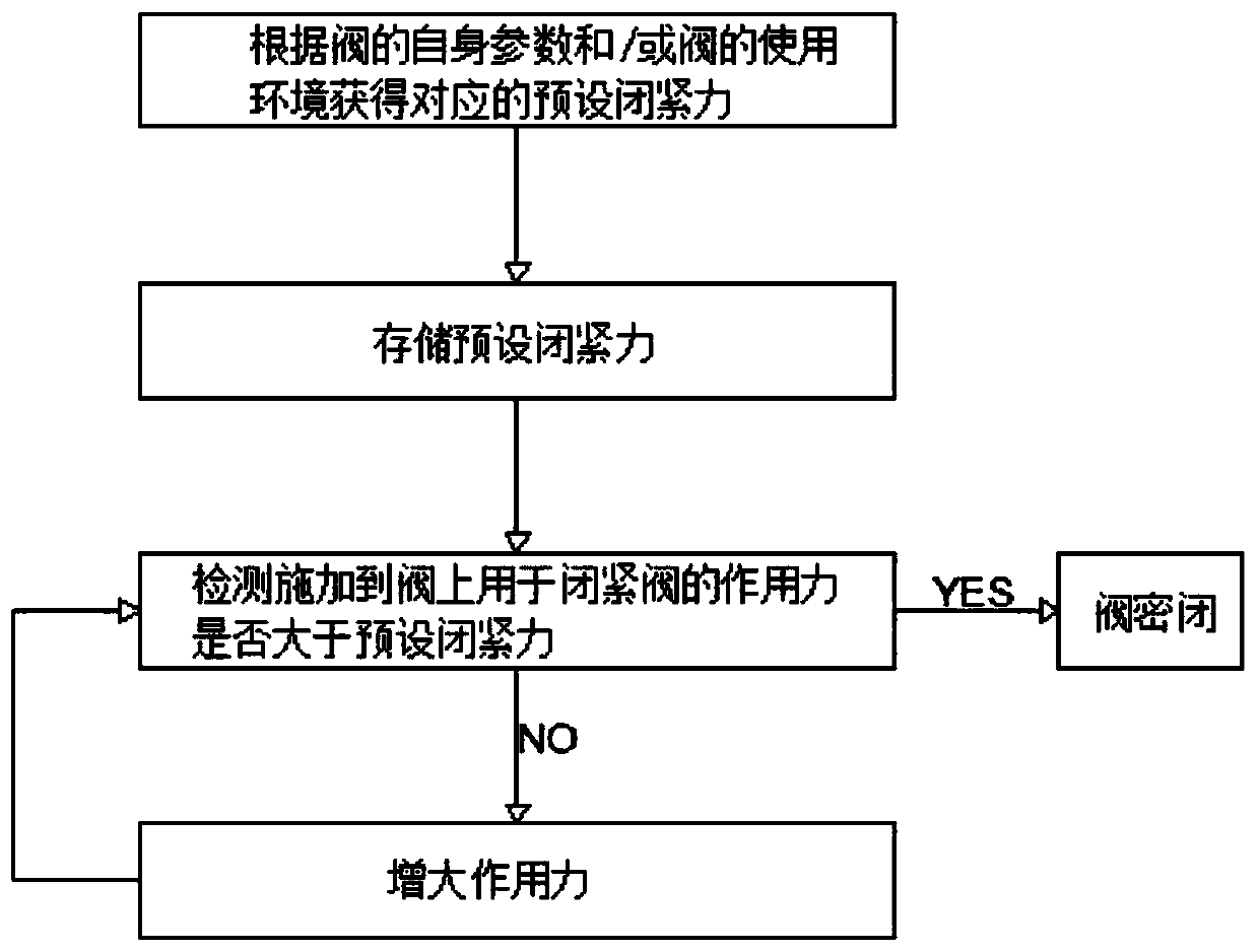
[0030] The implementation of the valve actuation method specifically includes:
[0031] The control system obta...
Embodiment 2
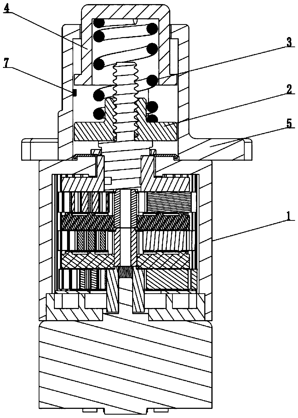
[0036] see image 3 , image 3 It is a cross-sectional view of the valve actuator of this embodiment. As shown in the figure, the valve actuating device includes a driving part 1, a lifting part 2, an elastic part 3, a valve body 4, a valve seat 5 and a Hall sensor 7, the driving part 1 is connected with the lifting part 2, and the elastic part 3 is set Between the jacking member 2 and the valve body 4 , the elastic member 3 is a magnetic spring, the valve body 4 is set in the valve seat 5 and protrudes from the top of the valve seat 5 , and the Hall sensor 7 is set on the valve seat 5 . When the valve actuating device in this embodiment is used to close the valve, the driver 1 and the Hall sensor 7 of the valve actuating device in this embodiment are connected to the control system, and a plurality of preset closing and tightening devices are stored in the control system. force.
[0037] The implementation of the valve actuation method specifically includes:
[0038] The ...
Embodiment 3
[0044] see Figure 4 , Figure 4It is a cross-sectional view of the valve actuator of this embodiment. As shown in the figure, the valve actuating device includes a driving part 1, a lifting part 2, an elastic part 3, a valve body 4, a valve seat 5, a photoelectric sensor 8 and a photoelectric sensor 9, the driving part 1 is connected with the lifting part 2, The elastic part 3 is set between the lifting part 2 and the valve body 4, the valve body 4 is set in the valve seat 5 and protrudes from the top of the valve seat 5, the photoelectric sensor 8 is set on the lifting part 2, and the photoelectric sensor 9 is set on the valve body 4. When the valve actuator in this embodiment is used to close the valve, the driver 1, the photoelectric sensor 8 and the photoelectric sensor 9 of the valve actuator in this embodiment are connected to the control system, and there are preset values stored in the control system. Set the closing force.
[0045] The implementation of the val...
PUM
 Abstract
Description
Claims
Application Information
 - R&D
- Intellectual Property
- Life Sciences
- Materials
- Tech Scout
- Unparalleled Data Quality
- Higher Quality Content
- 60% Fewer Hallucinations
Browse by: Latest US Patents, China's latest patents, Technical Efficacy Thesaurus, Application Domain, Technology Topic, Popular Technical Reports.
© 2025 PatSnap. All rights reserved.Legal|Privacy policy|Modern Slavery Act Transparency Statement|Sitemap|About US| Contact US: help@patsnap.com