Supercharge Your Innovation With Domain-Expert AI Agents!

Vacuum Cleaner Nozzle Equipped With A Main Suction Channel And A Secondary Suction Channel

A technology for vacuuming channels and vacuum cleaners, applied in the direction of suction nozzles, etc., can solve problems such as insufficient to ensure large waste, and achieve the effects of improving dusting performance, increasing air flow speed, and optimizing dusting efficiency.

Inactive Publication Date: 2019-10-29
SEB SA
View PDF8 Cites 2 Cited by
  • Summary
  • Abstract
  • Description
  • Claims
  • Application Information

AI Technical Summary

Problems solved by technology

[0006] However, when the vacuum cleaner equipped with such a suction nozzle has a relatively small suction flow rate, the dust collection efficiency of such a vacuum cleaner nozzle, and especially the dust collection efficiency at the auxiliary suction channel, may sometimes be insufficient. to ensure that large wastes (approximately a few grams) are inhaled

Method used


Image

  • Vacuum Cleaner Nozzle Equipped With A Main Suction Channel And A Secondary Suction Channel
  • Vacuum Cleaner Nozzle Equipped With A Main Suction Channel And A Secondary Suction Channel
  • Vacuum Cleaner Nozzle Equipped With A Main Suction Channel And A Secondary Suction Channel

Examples


Embodiment Construction

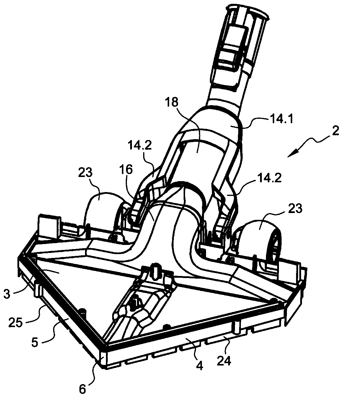
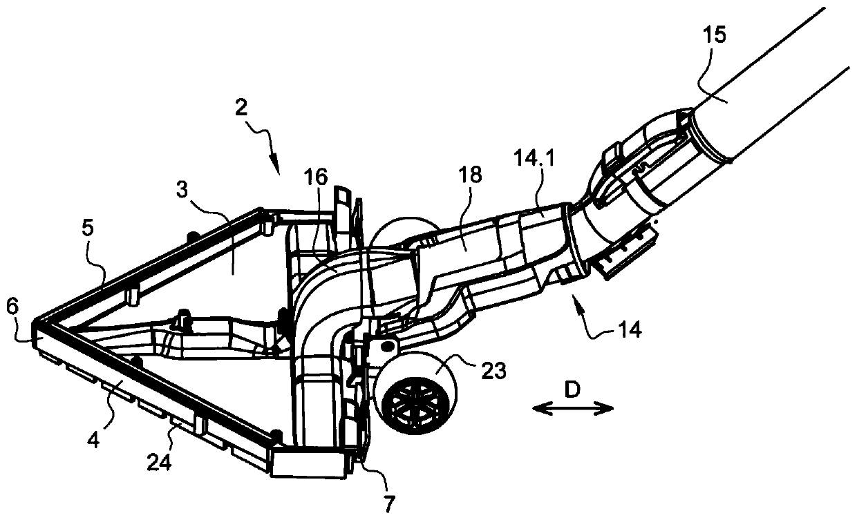
[0046] Figure 1 to Figure 6 A vacuum cleaner nozzle 2 is shown, comprising a base plate 3, eg made of plastic material, having a generally triangular shape. The base plate 3 comprises a first side edge 4 and a second side edge 5 forming the front tip 6 of the vacuum cleaner nozzle 2 and a rear edge 7 which is substantially perpendicular to the vacuum cleaner nozzle 2 in the direction of movement D. Advantageously, the first side edge 4 and the second side edge 5 of the bottom plate 3 form an acute angle.

[0047] The base plate 3 is notably equipped with a lower surface 8 comprising a front part 9 which is substantially flat and has a substantially triangular shape and a rear part 11 which has a substantially rectangular shape.

[0048]The floor 3 also comprises a main suction channel 12 which extends over the rear part 11 of the lower surface 8 and opens into the rear part 11 of the lower surface 8 . Advantageously, the main suction duct 12 extends along a first direction...


PUM


Abstract

A vacuum cleaner nozzle (2) includes a bottom plate (3), wherein the bottom plate (3) has a substantially triangular shape, and is equipped with a lower surface (8), a main dust suction passage (12),and an auxiliary dust suction passage (13). The main suction channel (12) extends transversely to the moving direction of the cleaner nozzle (2). The auxiliary suction channel (13) extends substantially parallel to the moving direction and is fluidly connected to the main suction channel (12). The lower surface (8) of the bottom plate (3) includes a front portion (9), which extends from the frontedge (12a) of the main suction channel (12) to the vicinity of the front tip (6) of the vacuum cleaner nozzle; the front portion (9) of the lower surface (8) is substantially flat and inclined so thatwhen the bottom plate (3) is set on the surface to be cleaned, the front tip (6) of the vacuum cleaner nozzle (2) is closer to the surface to be cleaned than the front edge (12a) of the main suctionchannel (12).

Description

technical field [0001] The invention relates to the field of vacuum cleaners equipped with vacuum cleaner nozzles, also called suction heads, which allow the suction of dust and small-sized waste present on surfaces. Background technique [0002] Vacuum cleaners equipped with vacuum cleaner nozzles are well known in the market, and they allow cleaning of surfaces by vacuuming to remove dust and small-grained waste trapped on the surface. The surface to be vacuumed can be, for example, a tiled floor, floor, laminate, carpet or carpet. [0003] Conventionally, a vacuum cleaner nozzle includes a connecting sleeve and a base plate equipped with a lower surface and at least one suction channel communicating with the connecting sleeve and opening to the lower surface of the base plate. The lower surface of the base plate is intended to be located adjacent to the surface to be vacuumed during use of the vacuum cleaner nozzle. [0004] From the document FR2980353 a base plate of a...

Claims


Application Information

Patent Timeline
Patent Type & Authority Applications(China)
IPC IPC(8): A47L9/02
CPCA47L9/02
Inventor 克里斯泰勒·菲利普维吉妮·波特拉让-达米安·维维耶
Owner SEB SA
Features
  • R&D
  • Intellectual Property
  • Life Sciences
  • Materials
  • Tech Scout
  • Unparalleled Data Quality
  • Higher Quality Content
  • 60% Fewer Hallucinations
Learn More