Article retainer assembly for refrigerators

a technology for refrigerators and retainers, which is applied in the field of refrigerators, can solve the problems of preventing the refrigerator door from closing properly, affecting the use of the refrigerator, so as to achieve the effect of convenient retrieval and easy shifting

Active Publication Date: 2008-04-15
MAYTAG
View PDF26 Cites 109 Cited by
  • Summary
  • Abstract
  • Description
  • Claims
  • Application Information

AI Technical Summary

Benefits of technology

[0008]The present invention is directed to an article retainer assembly for a shelf in a refrigerator including a cabinet shell within which is positioned a liner having top, bottom and opposing side walls that define, at least in part, a refrigerated compartment. The shelf is positioned in the refrigerated compartment for supporting articles to be refrigerated. The shelf includes a generally upper planar portion defined, at least in part, by a front edge section. In accordance with the invention, the article retainer assembly extends across the fr

Problems solved by technology

Although useful from an organizational standpoint, when in the lowered position, the retaining member may block a user from readily accessing items stored on lower shelves.
However, retaining m

Method used


Image

  • Article retainer assembly for refrigerators
  • Article retainer assembly for refrigerators
  • Article retainer assembly for refrigerators

Examples


first embodiment

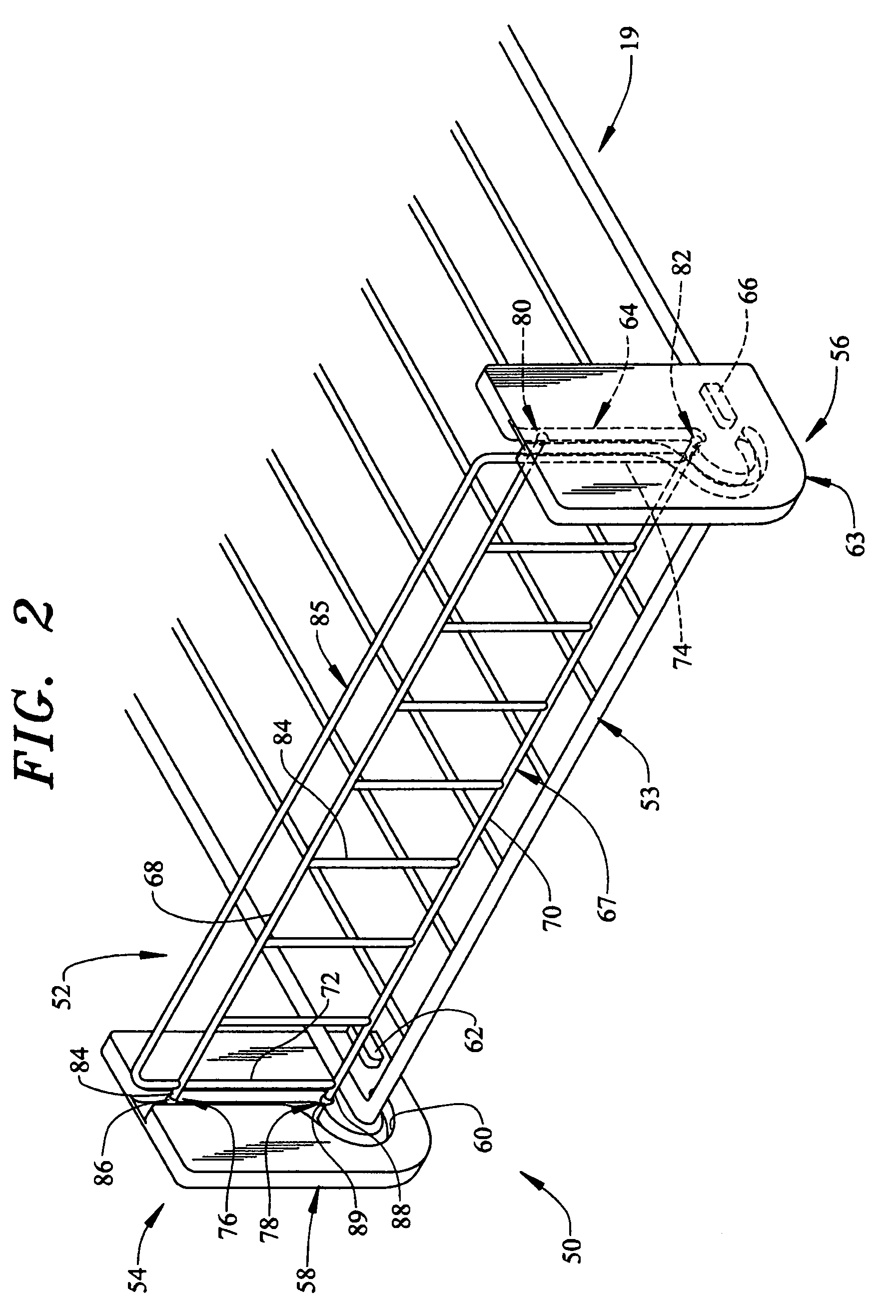
[0027]In accordance with the first embodiment, retaining member 52 is shown to include a plurality of intermediate members, such as indicated at 84, that extend between and interconnect top and bottom sections 68 and 70. Retaining member 52 is also shown to include an upper U-shaped bar 85. In any event, it should be understood that guide elements 76 and 80, pivot posts 78 and 82 and guide tracks 60 and 64 are respectively, similarly constructed such that a discussion will continue with respect to guide element 76, pivot post 78 and guide track 60 with an understanding that the opposing guide element 80, pivot post 82 and guide track 64 are similarly arranged. As shown, guide element 76 includes a shaft portion 84 that terminates in a head portion 86, with head portion 86 nesting within guide track 60. Likewise, pivot post 78 includes a shaft portion 88 which terminates in a head portion 89 which also nests within guide track 60. In a manner that will be discussed more fully below, ...

second embodiment

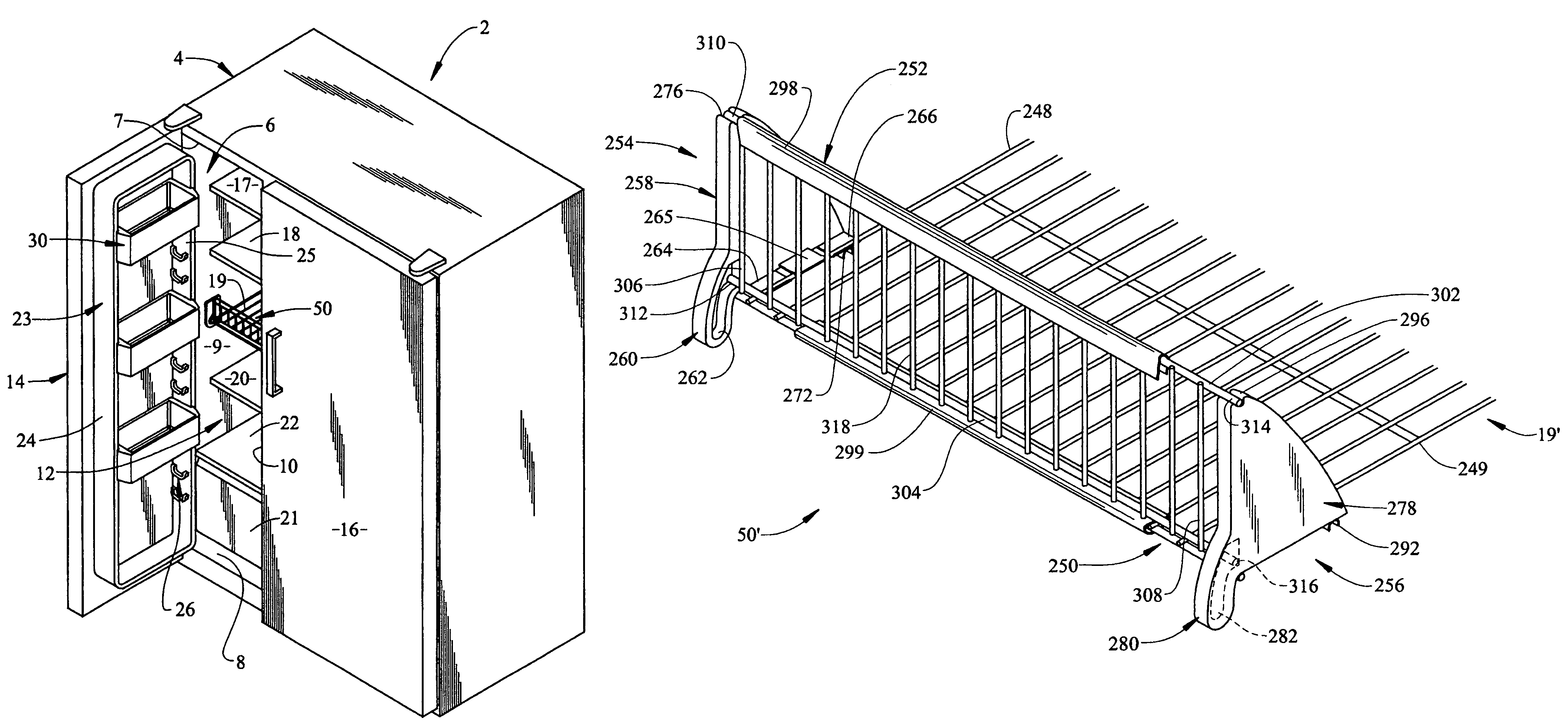
[0031]Reference will now be made to FIGS. 7-12 in describing the present invention. A shelf 19′ includes opposing side sections 248 and 249 and a front edge section 250. Shelf 19′ is provided with an article retainer assembly 50′ that includes a retaining member 252 which extends across front edge section 250 of shelf 19′. Retaining member 252 is supported by first and second support brackets 254 and 256 which snap-fittingly connect to shelf 19′. As shown, first bracket 254 includes a main body portion 258 and an arcuate finger portion 260 extending therefrom. Finger portion 260 includes a guide track 262 formed therein. Additionally, main body portion 258 includes first, second and third tab portions 264-266 which extend substantially perpendicularly and laterally inward. Each tab portion 264-266 includes a respective flange portion 268-270. Furthermore, third tab portion 266 is provided with a lower holding element or clip 272 having a first retention channel 274. A second retenti...


PUM


Abstract

An article retainer assembly for a refrigerator shelf includes a pair of support brackets and a retaining member. The support brackets are preferably mounted at opposing side portions of a refrigerator shelf, with the retaining member extending therebetween and across a front edge section of the shelf. The support brackets include corresponding guide tracks having first and second portions adapted to support the retaining member in an upright, lowered or stowed configuration. In the upright position, the retaining member prevents articles resting upon the shelf from moving beyond the front edge section. In the lowered position, unobstructed access is provided to the articles on the shelf and, in the stowed position, the retaining member is held in place below the shelf.

Description

CROSS-REFERENCE TO RELATED APPLICATIONS[0001]The present application constitutes a continuation-in-part of U.S. patent application Ser. No. 11 / 390,387, filed Mar. 28, 2006, now U.S. Pat. No. 7,198,340.BACKGROUND OF THE INVENTION[0002]1. Field of the Invention[0003]The present invention pertains to the art of refrigerators and, more particularly, to a movable front retainer assembly for a refrigerator shelf.[0004]2. Discussion of the Prior Art[0005]It is known to provide a refrigerator shelf with a tilt-down front retaining member. It is also known to provide a freezer shelf with a retaining member that can be shifted from an article retaining position to allow enhanced access to articles on the shelf. Therefore, such front is retainers securely retain articles on the shelves, while also providing a user easy access. In most cases, the retaining member is pivoted forward from an initial, upright position, to a second or lowered position. Although useful from an organizational standpo...

Claims


Application Information

Patent Timeline
IPC IPC(8): A47B96/02
CPCF25D25/02F25D2325/023A47B96/025
Inventor ERTZ, LAWRENCE J.
Owner MAYTAG
Why Eureka
Try Eureka