Backlight adjustment structure and display device

A backlight adjustment and display device technology, which is applied in light guides, optics, optical components, etc., can solve the problems of anti-peeping display devices such as thick size, easy to confuse, and low pixel density, and achieve the goal of avoiding small pixel density and thinning thickness Effect

Active Publication Date: 2019-11-08
BOE TECH GRP CO LTD
View PDF4 Cites 1 Cited by
  • Summary
  • Abstract
  • Description
  • Claims
  • Application Information

AI Technical Summary

Problems solved by technology

[0007] The embodiment of the present invention provides a backlight adjustment structur

Method used


Image

  • Backlight adjustment structure and display device
  • Backlight adjustment structure and display device
  • Backlight adjustment structure and display device

Examples


specific Embodiment

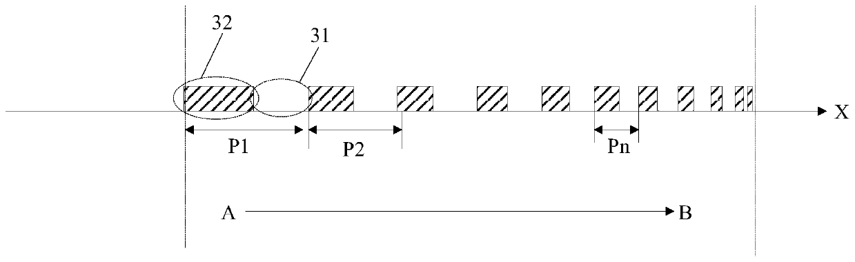
[0074] Assuming that the refractive index of the waveguide plate 1 is n1=1.52, the height of the focal point is f=30um, and the transmission angle of light in the waveguide plate θ1=65°, according to the above calculation formula, the convergence angle can be calculated from θ-~θ+ corresponding to the grating cycle parameters, such as Figure 16 shown.

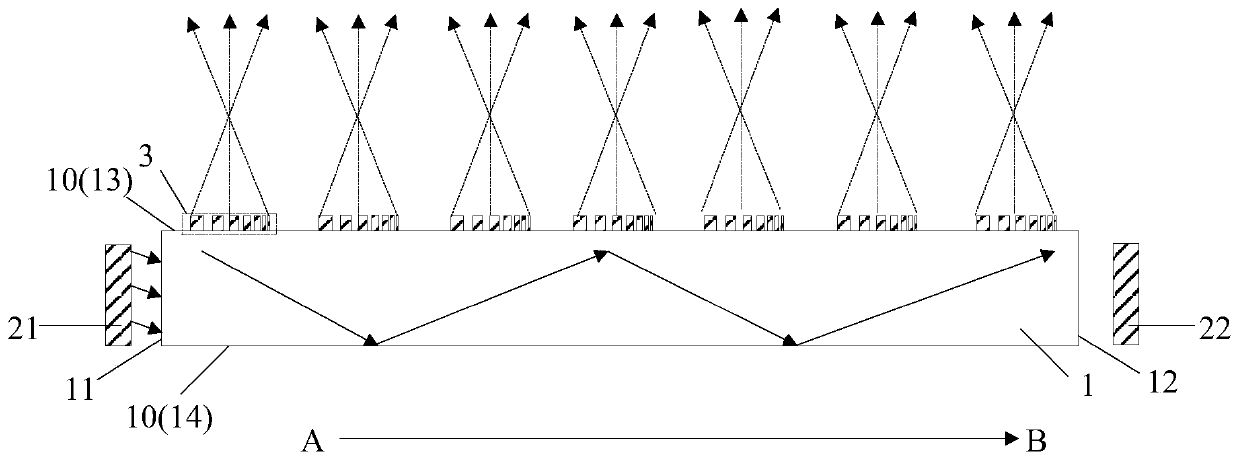
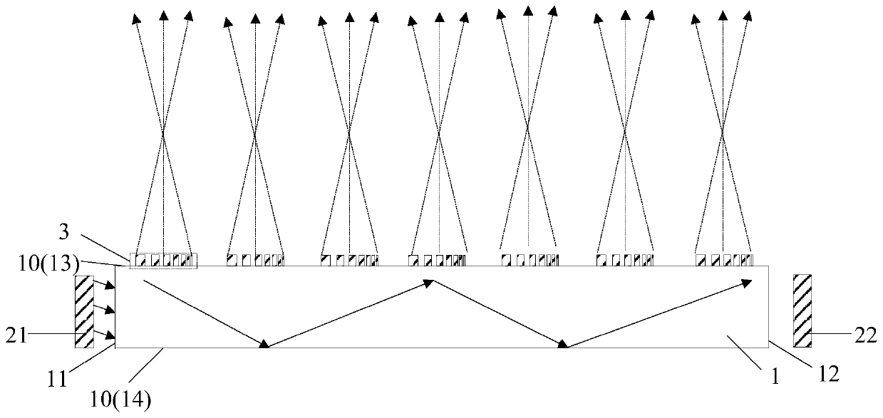
[0075] Such as Figure 17-Figure 19 Shown is the simulation result based on the above design method. When the light in the waveguide plate 1 is transmitted forward, the gradient grating structure 3 above the waveguide plate 1 presents a converging light-taking mode ( Figure 17 , Figure 18 ), at this time, the imaging anti-peeping display mode; when the light in the waveguide plate 1 is reversely transmitted, the gradient grating structure 3 above the waveguide plate 1 is imaged in a scattering light-taking mode ( Figure 19 ), the display mode is shared. The duty cycle of the gradient grating structure 3 with variable p...


PUM


Abstract

The invention discloses a backlight adjustment structure and a display device in order to solve the problems that in the prior art, an anti-peep display device is thick, a share mode is easily confused with an anti-peep mode, and in the display process, the pixel density is low. The backlight adjustment structure comprises a waveguide plate, a first light source, a second light source and a plurality of gradient grating structures, wherein the waveguide plate comprises a first side light-incidence surface, a second side light-incidence surface and a surface, the first side light-incidence surface is opposite to the second side light-incidence surface, and the surface is connected with the first side light-incidence surface and the second side light-incidence surface; the first light sourceis on the first side light-incidence surface of the waveguide plate, and the second light source is on the second first side light-incidence surface of the waveguide plate; the gradient grating structures are on the surface of the waveguide plate and in the direction from the first light source to the second light source, and the grating periods in the gradient grating structures are gradually shortened.

Description

technical field [0001] The invention relates to the field of peep-proof display, in particular to a backlight adjustment structure and a display device. Background technique [0002] With the advancement of technology, displays have become the main terminal for disseminating information. At present, information security is getting more and more attention in some important fields. In order to prevent personal and national information from being peeped by criminals, more and more anti-peeping technologies are applied to displays. [0003] Anti-peeping display devices in the prior art usually use resin lenses with a certain thickness arranged in the display device to realize different display functions, among which, a resin lens with a short focal length is used to realize a shared display mode, and a resin lens with a long focal length is used to realize Anti-peeping display mode, but the anti-peeping display device with this structure has the following problems: [0004] 1....

Claims


Application Information

Patent Timeline
IPC IPC(8): G02F1/13G02F1/13357G02B6/00
CPCG02F1/1323G02F1/133615G02B6/0058G02B6/0035G02B6/0068
Inventor 孟宪东谭纪风王维凌秋雨孟宪芹陈小川
Owner BOE TECH GRP CO LTD
Why Eureka
Try Eureka