Gyroscope drift correction method, device, photoelectric pod and aircraft

A technology of drift correction and photoelectric pod, which is applied in the field of gyroscope drift correction method, photoelectric pod and aircraft, and can solve the problems of image center drift, task load space angular rate deviation, and low precision, and achieve zero point drift correction Effect

Active Publication Date: 2020-03-20
CHENGDU JOUAV AUTOMATION TECH
View PDF10 Cites 0 Cited by
  • Summary
  • Abstract
  • Description
  • Claims
  • Application Information

AI Technical Summary

Problems solved by technology

The flight environment of the aircraft is complex and changes greatly, resulting in complex changes in the external ambient temperature of the photoelectric pod
[0003] The photoelectric pod uses a gyroscope to measure the spatial angular rate of the task load, but the zero position of the gyroscope will drift with temperature and time, resulting in a deviation of the spatial angular rate of the task load, and the drift of the center of the video image task equipment screen. Compensate for the zero drift phenomenon
[0004] However, current methods of compensating for gyroscope zero drift either have low accuracy or take a long time, resulting in low production efficiency

Method used

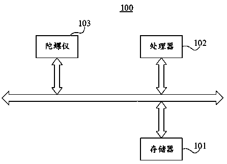

Image

  • Gyroscope drift correction method, device, photoelectric pod and aircraft
  • Gyroscope drift correction method, device, photoelectric pod and aircraft
  • Gyroscope drift correction method, device, photoelectric pod and aircraft

Examples


Embodiment Construction

[0033] In order to make the purposes, technical solutions and advantages of the embodiments of the present application clearer, the technical solutions in the embodiments of the present application will be clearly and completely described below in conjunction with the drawings in the embodiments of the present application. Obviously, the described embodiments It is a part of the embodiments of this application, not all of them. The components of the embodiments of the application generally described and illustrated in the figures herein may be arranged and designed in a variety of different configurations.

[0034] Accordingly, the following detailed description of the embodiments of the application provided in the accompanying drawings is not intended to limit the scope of the claimed application, but merely represents selected embodiments of the application. Based on the embodiments in this application, all other embodiments obtained by persons of ordinary skill in the art w...


PUM


Abstract

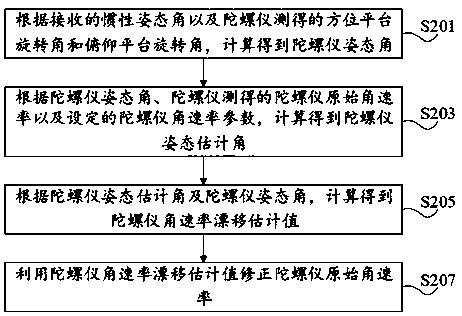
The application, which relates to the technical field of automatic control, provides a gyroscope drift correction method and device, a photoelectric pod and an aircraft. Calculation is carried out byusing a received inertia attitude angle and an azimuth platform rotation angle and a pitching platform rotation angle measured by a gyroscope to obtain a gyroscope attitude angle; a gyroscope attitudeestimation angle is calculated according to the gyroscope attitude angle, a gyroscope original angular rate measured by the gyroscope and a set gyroscope angular rate parameter; a gyroscope angular rate drift estimation angle is calculated according to the gyroscope attitude estimation angle and the gyroscope attitude angle; and then the original angular rate of the gyroscope is corrected by using the gyroscope angular rate drift estimation angle. Compared with the prior art, the gyroscope drift correction method and device have the following advantage: the zero drift of the gyroscope can becorrected in real time on the premise that human intervention is not needed.

Description

technical field [0001] The present application relates to the technical field of automatic control, in particular, to a gyroscope drift correction method and device, a photoelectric pod and an aircraft. Background technique [0002] The photoelectric pod is installed on the aircraft and is generally used to search and track targets. The flight environment of the aircraft is complex and changes greatly, resulting in complex changes in the external ambient temperature of the photoelectric pod. [0003] The photoelectric pod uses a gyroscope to measure the spatial angular rate of the task load, but the zero position of the gyroscope will drift with temperature and time, resulting in a deviation of the spatial angular rate of the task load, and the drift of the center of the video image task equipment screen. Compensate for the zero drift phenomenon. [0004] However, the current methods of compensating for gyroscope zero drift either have low accuracy or take a long time, res...

Claims


Application Information

Patent Timeline
Patent Type & Authority Patents(China)
IPC IPC(8): G01C25/00
CPCG01C25/00
Inventor 刘述超衡思兰
Owner CHENGDU JOUAV AUTOMATION TECH
Why Eureka
Try Eureka