
Cushion layer spinning method

A cushion layer and spinning forming technology, applied in the field of cushion layer spinning, can solve the problems of increased machining or grinding and polishing, difficult control of wall thickness uniformity, and reduced product qualification rate, and achieves the effect of solving poor inner surface quality.

Active Publication Date: 2019-12-06
NORTHWESTERN POLYTECHNICAL UNIV +1
View PDF5 Cites 0 Cited by
  • Summary
  • Abstract
  • Description
  • Claims
  • Application Information

AI Technical Summary

Problems solved by technology

These protrusions reduce the quality of the inner surface of the part, and subsequent machining or grinding and polishing processes need to be added, which reduces the production efficiency. There is a problem of wall thickness out of tolerance, which leads to a decrease in product qualification rate

Method used

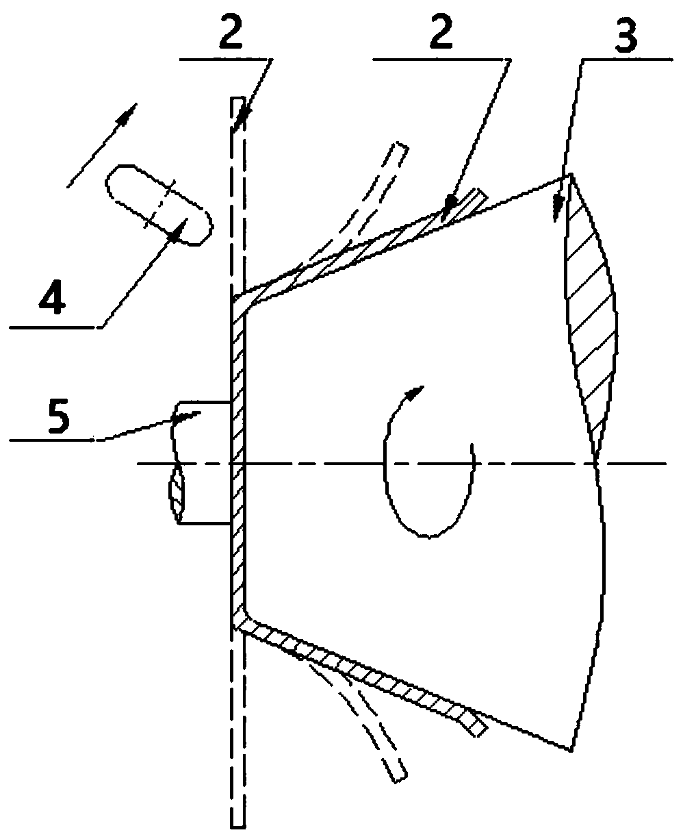
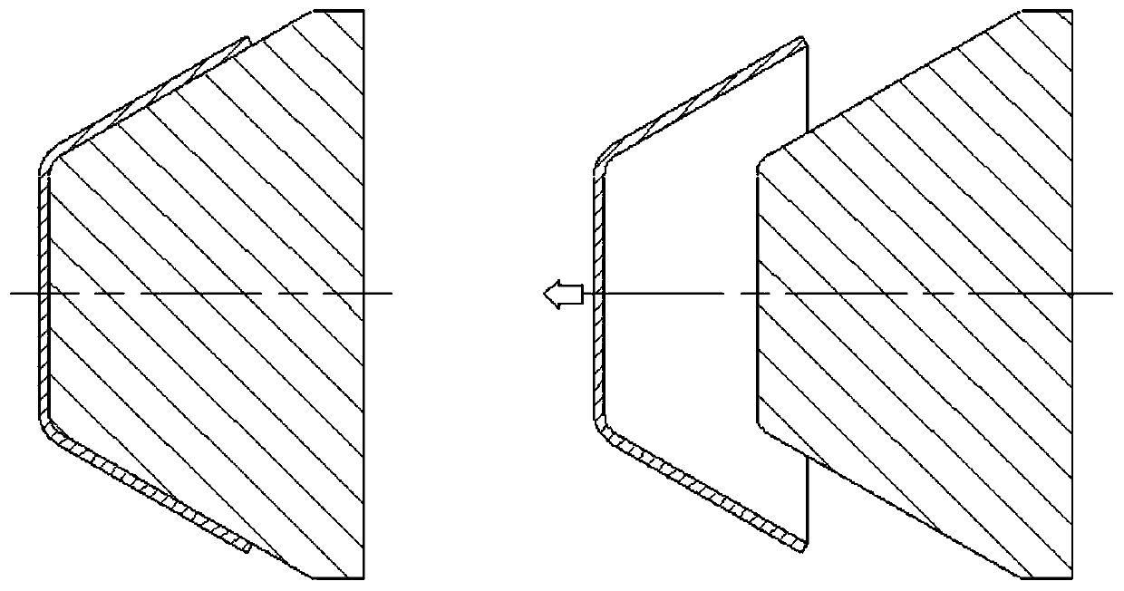
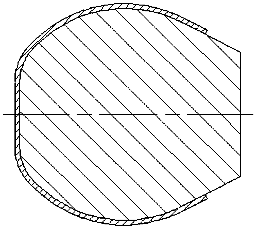

Image

  • Cushion layer spinning method
  • Cushion layer spinning method
  • Cushion layer spinning method

Examples


Embodiment Construction

[0037] In order to more clearly understand the above objects, features and advantages of the present invention, the present invention will be described in detail below in conjunction with the accompanying drawings and specific embodiments. It should be noted that, in the case of no conflict, the embodiments of the present application and the features in the embodiments can be combined with each other.

[0038] Unless otherwise defined, all technical and scientific terms used herein have the same meaning as commonly understood by one of ordinary skill in the technical field of the invention. The terms used herein in the description of the present invention are for the purpose of describing specific embodiments only, and are not intended to limit the present invention.

[0039] A cushion spinning method, comprising the following steps:

[0040] (1) Select the appropriate cushion material according to the material characteristics of the formal spinning parts, ensure that the mel...


PUM


Abstract

The invention relates to a cushion layer spinning method, particularly adopts a method for adding a cushion layer between a spinning die and a spinning piece, solves the problem that the spinning dieis split, resulting in low quality of the inner surface, and needs to consider the problem that after the cushion layer is added, the cushion layer is separated from the spinning piece, the inventionalso provides a method for selecting a low-melting-point material as a cushion layer, with the condition that the melting point of a cushion layer material is lower than the heat treatment temperatureof the spinning piece as the best, and in addition, since a plate blank cannot be demolded due to spinning forming, the deformation angle is larger than 90 degrees, and the deformation is very acute;if a method for performing synchronous spinning forming on a normal blank and the cushion layer material, the cushion layer is likely to wrinkle during the deformation process of the blank, and the cushion layer is locally folded, so that the wall thickness of the normal spinning piece is uncontrollable; and therefore, at first, the cushion layer material is subjected to spinning forming, and then the normal blank is subjected to spinning forming, so that a layer-by-layer spinning forming method capable of enabling the blank to be attached to the cushion layer in a layer-by-layer manner is formed.

Description

technical field [0001] The invention belongs to the technical field of spinning forming, and in particular relates to a cushion layer spinning method. Background technique [0002] Spinning is a metal plastic forming method used to form thin-walled hollow rotary parts (as attached figure 1 ). It is formed by applying pressure to the rotating blank with tools such as a rotary wheel to produce continuous local plastic deformation. Usually, the metal flat blank or prefabricated blank is clamped on the mold of the spinning machine first, and the mold and the blank are driven by the spindle to rotate, and then the rotary wheel exerts pressure on the blank with a certain trajectory and moving speed, so that the blank is produced continuously and point by point. Plastic deformation, so as to obtain hollow rotating body parts with various generatrix shapes. [0003] Metal spinning is usually used for open-shaped workpieces, multi-formed cylindrical parts and conical parts, that i...

Claims


Application Information

Patent Timeline
IPC IPC(8): B21D22/16
CPCB21D22/16
Inventor 陈福龙刘德贵李凯迪李金山唐斌樊江昆陈彪王毅寇宏超王军赖敏杰
Owner NORTHWESTERN POLYTECHNICAL UNIV
Learn More