
Rebar Bending Machine

A hoop bending machine and steel bar technology, applied in the field of steel bar bending, can solve the problem of laborious bending process of steel bar

Active Publication Date: 2020-10-20
江苏易明昌建设集团有限公司
View PDF10 Cites 2 Cited by
  • Summary
  • Abstract
  • Description
  • Claims
  • Application Information

AI Technical Summary

Problems solved by technology

[0003] In order to save manpower, the steel bar bending machine is basically used to bend the steel bar. Before the steel bar is bent, the steel bar is cut off first, and then the steel bar is manually placed on the steel bar bending machine for bending. After the bending is completed, the steel bar is manually removed from the steel bar. The hoop bending machine is removed, and the loading and unloading of steel bars need to be completed manually, which makes the whole steel bar bending process laborious.

Method used


Image

  • Rebar Bending Machine
  • Rebar Bending Machine
  • Rebar Bending Machine

Examples


Embodiment

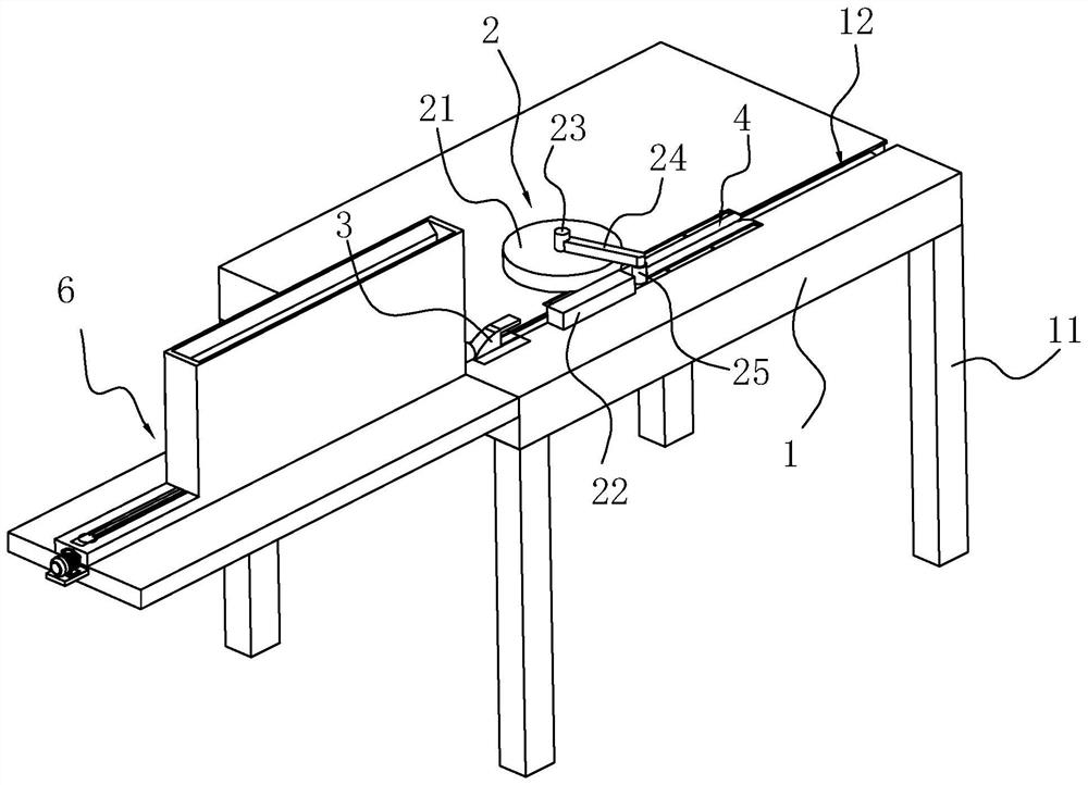
[0046] Embodiment: a kind of steel bar hoop bending machine, see attached figure 1 , including a workbench 1 arranged in a rectangular shape, four outriggers 11 fixedly connected to the four corners of the bottom of the workbench 1 for supporting the workbench 1, and a support for bending steel bars arranged on the top of the workbench 1 Bending mechanism 2, the support mechanism 4 that is arranged on the workbench 1 and is used to support the steel bar, the feed mechanism 6 that is arranged on the workbench 1 side and is used to send the steel bar into the top of the workbench 1 and is arranged on the workbench 1 The blanking block 3 on the table 1 is used to send the bent steel bar from the top of the workbench 1. The side of the top of the workbench 1 close to the feed mechanism 6 is the feed side, and the side away from the feed mechanism 6 is the discharge side. The blanking block 3 slides on the top of the workbench 1 along the feeding direction of the steel bar. There ...


PUM


Abstract

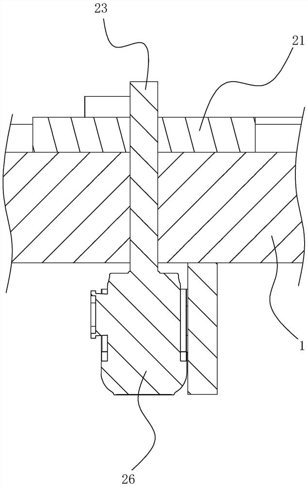
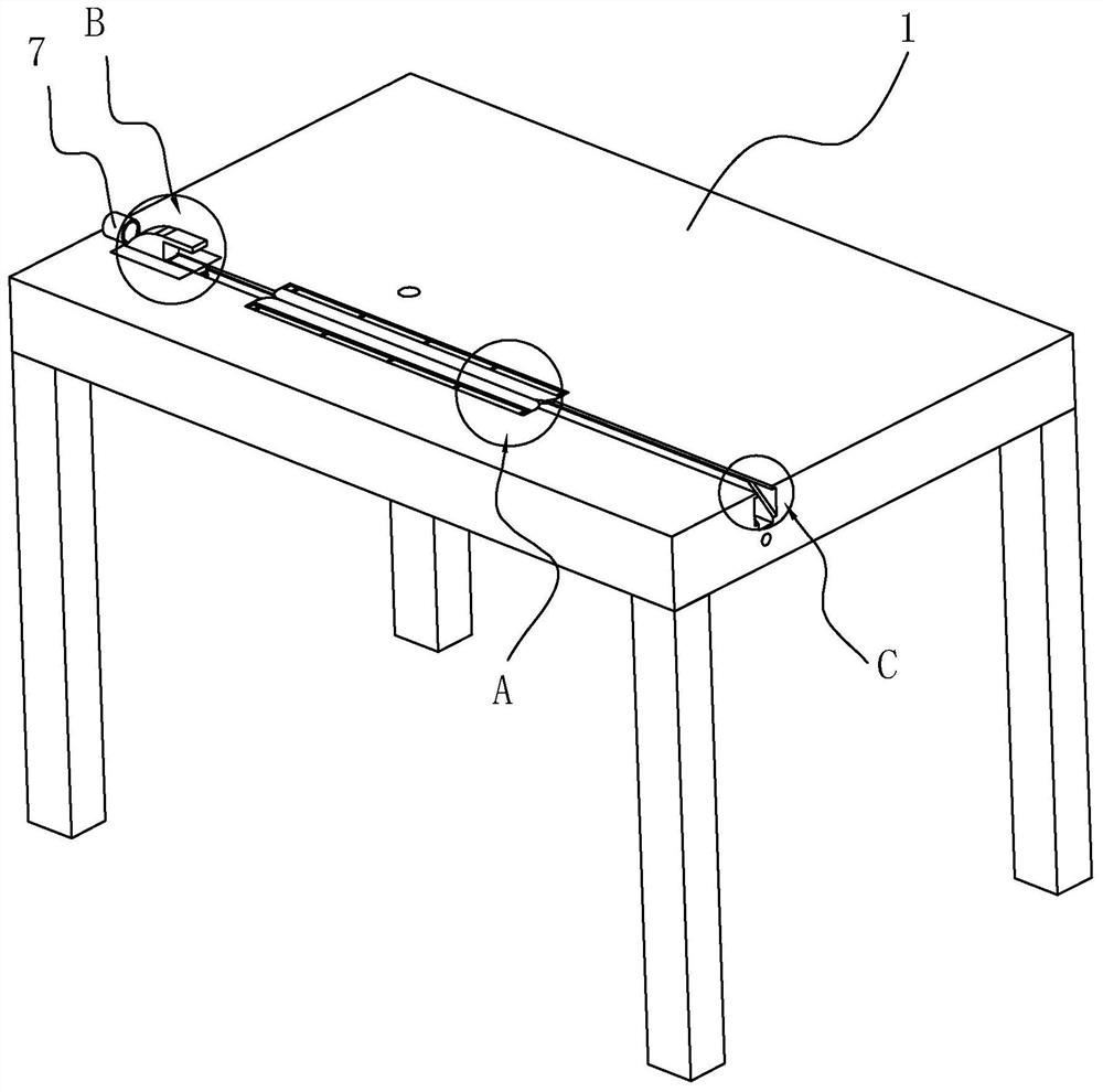
The invention discloses a steel bar bending machine, relates to the technical field of steel bar bending and solves the problem that the existing steel bar bending process is labor-consuming. The technical scheme is characterized in that the steel bar bending machine comprises a workbench, a fixed disc fixedly connected at the top of the workbench, a rotating shaft rotationally connected onto thefixed disc, a rotating motor arranged on the workbench and used for driving the rotating shaft to rotate, a limit rod fixedly connected to the top of the workbench, a connecting rod fixedly connectedto the top of the rotating shaft, a bending shaft fixedly connected to the bottom of the connecting rod as well as a discharging block arranged at the top of the workbench. A worker places steel barson the steel bar bending machine, the bending shaft rotates around the fixed disc to bend the steel bars, after bending of the steel bars, a pushing block pushes the bent steel bars to slide toward the side of the workbench and sends out the steel bars from the side of the workbench, and the worker is not required for discharging the steel bars, so that the steel bar bending process is more labor-saving.

Description

technical field [0001] The invention relates to the technical field of steel bar bending, more specifically, it relates to a steel bar hoop bending machine. Background technique [0002] In the current construction field, it is necessary to use a large number of steel bars in the concrete structure, and these steel bars need to be bent before they can be used in the concrete structure; on the construction site, the steel bar bending structure is usually done manually by construction workers , first bend the steel bar, and then cut it off. [0003] In order to save manpower, the steel bar bending machine is basically used to bend the steel bar. Before the steel bar is bent, the steel bar is cut off first, and then the steel bar is manually placed on the steel bar bending machine for bending. After the bending is completed, the steel bar is manually removed from the steel bar. The hoop bending machine is removed, and the feeding and unloading of the steel bars need to be comp...

Claims


Application Information

Patent Timeline
Patent Type & Authority Patents(China)
IPC IPC(8): B21F1/00B21F23/00
CPCB21F1/00B21F23/00
Inventor 吉欣
Owner 江苏易明昌建设集团有限公司
Learn More