Flexible telescopic mechanism used for bridge and bridge telescopic device

A technology for telescopic mechanisms and bridges, applied in bridges, bridge parts, bridge construction, etc., can solve the problems of weakening the horizontal impact effect of telescopic mechanisms, uneven seam width of telescopic devices, and weakening impact effects, etc., to ensure the gap width of beams Uniformity, improving service life and driving comfort, and reducing the effect of impact

Active Publication Date: 2019-12-10
ZHUZHOU TIMES NEW MATERIALS TECH
View PDF11 Cites 2 Cited by
  • Summary
  • Abstract
  • Description
  • Claims
  • Application Information

AI Technical Summary

Problems solved by technology

[0005] The bridge flexible expansion mechanism and bridge expansion device provided by the present invention can ensure the uniformity of the gap width of the beam body, can adapt to the certain displacement and rotation angle between the side beam and the middle beam of the bridge when the vehicle passes the car, weaken the impact effect, and improve the service life And driving comfort, reducing impact noise, can well solve the problems of uneven gap width and excessive impact response of the original expansion device, the flexible bushing makes the expansion mechanism "soft" deformation, weakens the horizontal impact effect of the expansion mechanism, Reduce the impact and vibration noise caused by the passing of the vehicle, and improve the comfort of the vehicle

Method used


Image

  • Flexible telescopic mechanism used for bridge and bridge telescopic device
  • Flexible telescopic mechanism used for bridge and bridge telescopic device
  • Flexible telescopic mechanism used for bridge and bridge telescopic device

Examples


Embodiment Construction

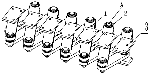
[0029] Combine below Figure 1 to Figure 8 Embodiments of the present invention are described in detail.

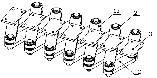
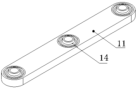
[0030] The flexible telescopic mechanism for the bridge includes a cross-grid-shaped cross-link assembly 1, which is characterized in that the connection position of the cross-link assembly 1 is connected by a flexible bush 2 with elastic body, and the flexible bush 2 passes through the interference Fitted into the connection position of the cross-link assembly 1, the flexible bushing 2 at the cross-connection position of the cross-connection rod assembly 1 is rotatably installed with the connecting seat 3 connected to the bridge beam body, and at the end of the cross-connection rod assembly 1 Install pin A with clearance fit in the flexible bushing 2 at the connecting position.

[0031]The above-mentioned flexible telescopic mechanism for bridges includes a cross-link assembly 1, a flexible bush 2, a connecting seat 3 and a pin A, and the flexible bush 2 is loaded into ...


PUM


Abstract

The invention discloses a flexible telescopic mechanism used for a bridge. The flexible telescopic mechanism comprises a crossed connecting rod assembly. The connecting positions of the crossed connecting rod assembly are connected through flexible linings. The flexible linings are arranged in the connecting positions of the crossed connecting rod assembly in an interference fit manner. Connectingseats connected with a bridge beam body are rotationally installed in the flexible linings at the crossed connecting positions of the crossed connecting rod assembly, and pin shafts are installed inthe flexible linings at the connecting positions of the end portions of the crossed connecting rod assembly in a clearance fit manner. By means of the flexible telescopic mechanism used for the bridge, the uniformity of the seam width of the beam body is ensured, the flexible telescopic mechanism can adapt to the certain displacement and rotating angle between an edge beam and a middle beam of thebridge when a vehicle passes through the bridge, the impact effect is weakened, the service life is prolonged, the driving comfort is improved, impact noise is lowered, the problems that the seam width of an original telescopic device is not uniform and the impact response is large can be well solved, flexible deformation of the telescopic mechanism is achieved through the flexible linings, the horizontal impact effect of the telescopic mechanism is weakened, the impact and vibration noise caused when the vehicle passes through the bridge are weakened, and the comfort of the vehicle is improved. The invention further provides a bridge telescopic device.

Description

technical field [0001] The invention relates to a flexible expansion mechanism and a bridge expansion device for bridges, which are suitable for large displacement bridges. Background technique [0002] Most of the gap width uniform distribution mechanisms of existing large-displacement bridge expansion devices use rubber or polyurethane springs, which are divided into compression type and shear type. When the compression type uniform distribution mechanism is used, the deformation of the compression spring is the smallest at the maximum or minimum slit width, where the uniform distribution ability of the uniform distribution mechanism is the smallest. At this time, uneven slit width may occur. When the shear type uniform distribution mechanism is used, the non-deformation position of the shear spring is set at 1 / 2 of the specified displacement of the slit width, so the uniform distribution force of the uniform distribution mechanism here is zero, which is not conducive to t...

Claims


Application Information

Patent Timeline
Patent Type & Authority Applications(China)
IPC IPC(8): E01D19/06
CPCE01D19/062
Inventor 孔令俊欧阳柳陈彦北
Owner ZHUZHOU TIMES NEW MATERIALS TECH
Why Eureka
Try Eureka