
fracture reducer

A technology of a reducer and a fracture end, which is applied in the field of medical devices and can solve problems such as minimally invasive reduction of the fracture segment

Active Publication Date: 2020-05-26
淮安市第二人民医院(淮安仁慈医院)
View PDF8 Cites 0 Cited by
  • Summary
  • Abstract
  • Description
  • Claims
  • Application Information

AI Technical Summary

Problems solved by technology

[0005] The technical problem to be solved by the present invention is to overcome the deficiencies of the prior art and provide a fracture reducer. Compared with the prior art, the movement and rotation of the joints on the outside drive the movement and rotation of the bones inside to reset , to solve the problem of minimally invasive reduction of the fracture segment

Method used


Image

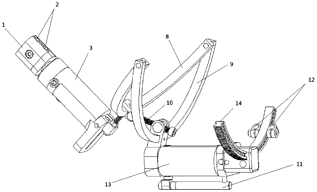
  • fracture reducer
  • fracture reducer
  • fracture reducer

Examples


Embodiment Construction

[0017] According to the fracture reducer of the present invention, the problem of minimally invasive reduction of the fracture segment is solved. Normally, after the fracture, the bone faces two different directions from the fracture, and at this time, it needs to be reset and fixed according to the original direction of the bone. The spatial mutual displacement between two fracture segments can be divided into displacement or rotation on six degrees of freedom, including displacement or rotation on the X axis, displacement or rotation on the Y axis, displacement or rotation on the Z axis, and displacement or rotation on the Z axis. position or turn.

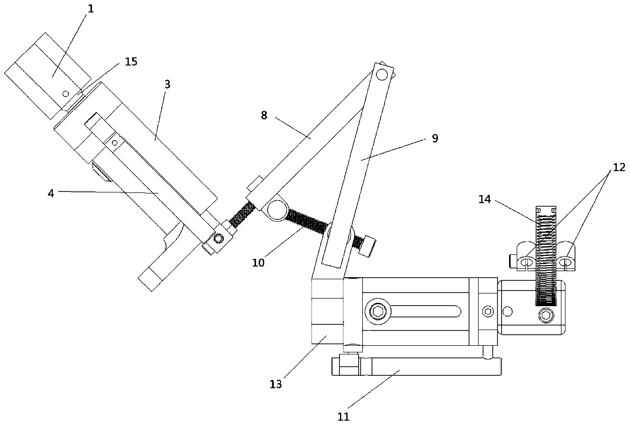
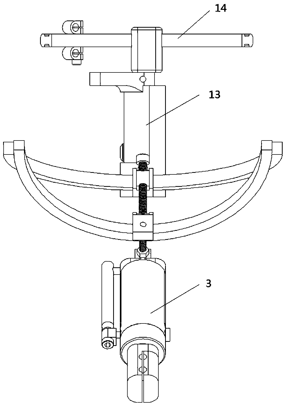
[0018] Such as Figure 1-5 As shown, it mainly includes a medial fixation part and a lateral fixation part, which are respectively used for the two ends of bone fractures. The medial fixation part and the lateral fixation part can be fixed at a certain angle.

[0019] Specifically, the inner fixing part has an inner nail clip 1...


PUM


Abstract

The invention provides a fracture reduction device. The fracture reduction device comprises an inner fixing part and an outer fixing part which are used at two ends respectively after bone fracture and can be fixed at a certain angle; the fracture reduction device is adjusted to ensure X, Y and Z coordinate origins of virtual coordinates of the reduction device are located in the center of fracture sections, the reduction device decomposes shift of the fraction sections into six-degree-of-freedom movement, then, six degrees of freedom are externalized to movement and rotation of each joint byfixing screws at two ends, and movement and rotation of each joint outside drive inside bones to move and rotate for reduction. According to the fracture reduction device, the movement and rotation ofeach joint outside drive inside bones to move and rotate for reduction, so that the problem of minimally invasive reduction of fracture sections is solved.

Description

technical field [0001] The invention relates to the field of medical instruments, in particular to a fracture reducer. Background technique [0002] The existing fracture reducer, as described in Patent Document 1 (CN101278858A), includes a telescopic guide rod and a semicircular needle seat track, and the telescopic guide rod is formed by connecting multiple sections of guide rods through connecting sleeves. The annular needle seat track is axially provided with an annular through groove along the annular circumferential end surface, and an arc-shaped rack is embedded in the annular through groove, and a needle seat positioning meshing with the arc-shaped rack is provided in the annular through groove. Gear, the needle seat positioning gear is connected with the arc-shaped needle seat buckled on the semi-circular needle seat track, the arc-shaped needle seat is radially fixedly connected with a cylindrical shell, and the inner sleeve of the cylindrical shell A lifting rod ...

Claims


Application Information

Patent Timeline
Patent Type & Authority Patents(China)
IPC IPC(8): A61B17/66
CPCA61B17/66
Inventor 周全
Owner 淮安市第二人民医院(淮安仁慈医院)
Learn More