Blade-movable lamp

A technology of blades and lamps, which is applied to lampshades, parts of lighting devices, lighting and heating equipment, etc., and can solve problems such as limiting visual effects

Pending Publication Date: 2019-12-20
浙江机电职业技术学院
View PDF0 Cites 0 Cited by
  • Summary
  • Abstract
  • Description
  • Claims
  • Application Information

AI Technical Summary

Problems solved by technology

The lampshade of the lamp is usually fixed, whi

Method used


Image

  • Blade-movable lamp
  • Blade-movable lamp
  • Blade-movable lamp

Examples


Embodiment 1

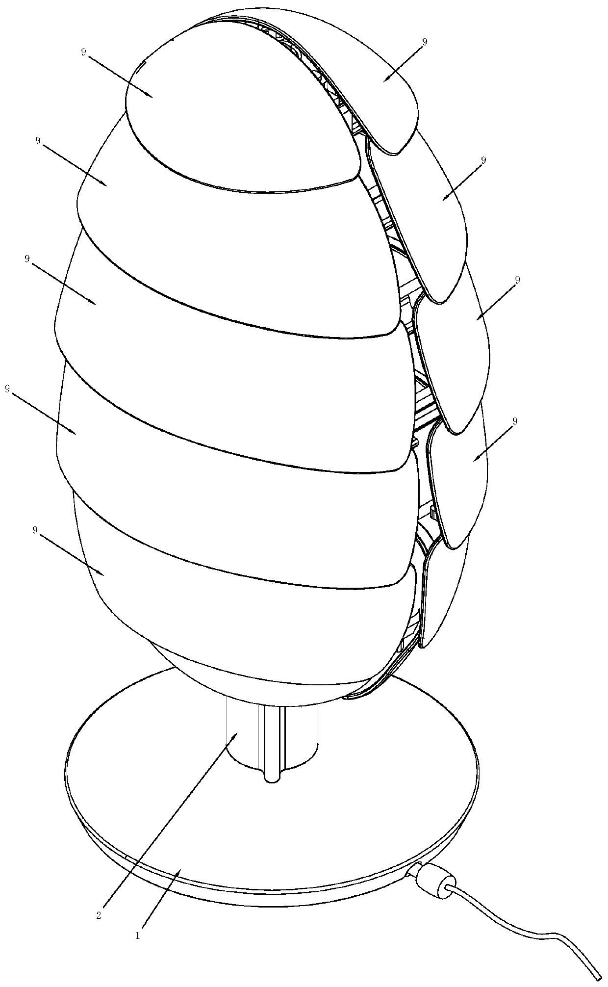
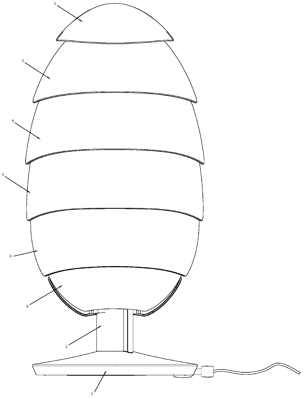
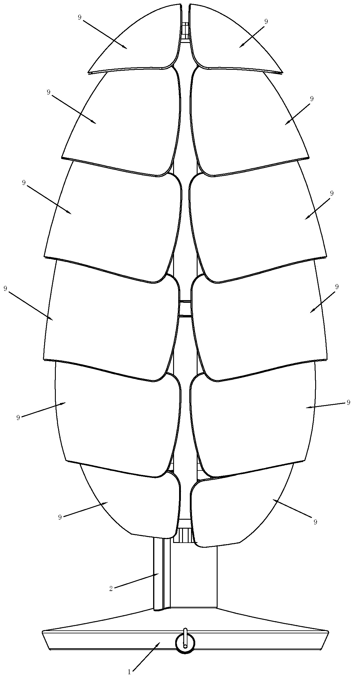
[0045] see Figure 1 to Figure 13 , a lamp with movable blades according to Embodiment 1 of the present invention, comprising a lamp holder 1, on which a light-emitting member is arranged, and on the lamp holder 1, a motor 5 and a rotating member 6 driven by the motor 5 are provided, The outer periphery of the rotating member 6 is provided with a track groove 61, the track groove 61 is at least partly inclined in the vertical direction, a connecting rod 91 is arranged in the track groove 61, and the other end of the connecting rod 91 is connected to the lampshade blade 9. When the motor 5 rotates, it drives the rotary member 6 to rotate, thereby making the lampshade blades 9 move in the track grooves 61 .

[0046] As an improvement, the track groove 61 is an annular groove, so that the motor 5 rotates in one direction to drive the lampshade blade 9 to move continuously.

[0047] As an improvement, the track groove 61 is inclined along the vertical direction, so that the lamps...


PUM


Abstract

The invention belongs to the technical field of lamps, and particularly relates to a blade-movable lamp. For the defect that a lampshade of an existing lamp is fixed, the following technical scheme isadopted. The blade-movable lamp comprises a lamp holder; a light emitting part is arranged on the lamp holder; a motor and a rotating piece driven by the motor are further arranged on the lamp holder; a track groove is formed in the periphery of the rotating piece; the track groove is at least partially inclined in the vertical direction; a connecting rod is arranged in the track groove; the other end of the connecting rod is connected with a lampshade blade; and when the motor rotates, the rotating piece is driven to rotate, so that the lampshade blade moves in the track groove. The blade-movable lamp has the beneficial effects that the lampshade blade can move up and down in the track groove under the driving of the motor.

Description

technical field [0001] The invention belongs to the technical field of lamps, and in particular relates to a lamp with movable blades. Background technique [0002] Most of the existing lamps change the light to obtain various visual effects. The lampshade of the lamp is usually fixed, thus limiting the acquisition of some visual effects. Contents of the invention [0003] The invention aims at the problem that the lampshade of the existing lamp is fixed, and provides a lamp with movable blades to obtain novel visual effects. [0004] In order to achieve the above object, the present invention adopts the following technical solution: a lamp with movable blades, including a lamp holder, a light-emitting part is arranged on the lamp holder, a motor and a rotating part driven by the motor are also arranged on the lamp holder, so that A track groove is set on the outer periphery of the rotating member, and at least part of the track groove is inclined in the vertical directi...

Claims


Application Information

Patent Timeline
IPC IPC(8): F21S6/00F21V21/06F21V19/00F21V21/30F21V3/00
CPCF21S6/00F21V3/00F21V19/00F21V21/06F21V21/30
Inventor 诸葛耀泉杨小娥卢徐斌
Owner 浙江机电职业技术学院
Why Eureka
Try Eureka