A near-eye display device and projection feedback method

A near-eye display and projection image technology, applied in optical components, instruments, optics, etc., can solve the problems of degradation of projection quality, deviation of the motion trajectory and state of the fiber optic scanner from the ideal mode, and difficulty in stabilizing the driving signal to scan light, etc., and achieve a simple structure. , Solve the effect of projection quality degradation

Active Publication Date: 2021-10-29
CHENGDU IDEALSEE TECH
View PDF17 Cites 0 Cited by
  • Summary
  • Abstract
  • Description
  • Claims
  • Application Information

AI Technical Summary

Problems solved by technology

[0003] As an image source, fiber optic scanners are easily affected by environmental factors such as temperature, humidity, vibration, driving fluctuations, and aging fatigue. , so that projection quality degradation occurs during long hours of work

Method used


Image

  • A near-eye display device and projection feedback method
  • A near-eye display device and projection feedback method
  • A near-eye display device and projection feedback method

Examples


Embodiment Construction

[0053] The following will clearly and completely describe the technical solutions in the embodiments of the present invention with reference to the accompanying drawings in the embodiments of the present invention. Obviously, the described embodiments are only some, not all, embodiments of the present invention. Based on the embodiments of the present invention, all other embodiments obtained by persons of ordinary skill in the art without creative efforts fall within the protection scope of the present invention.

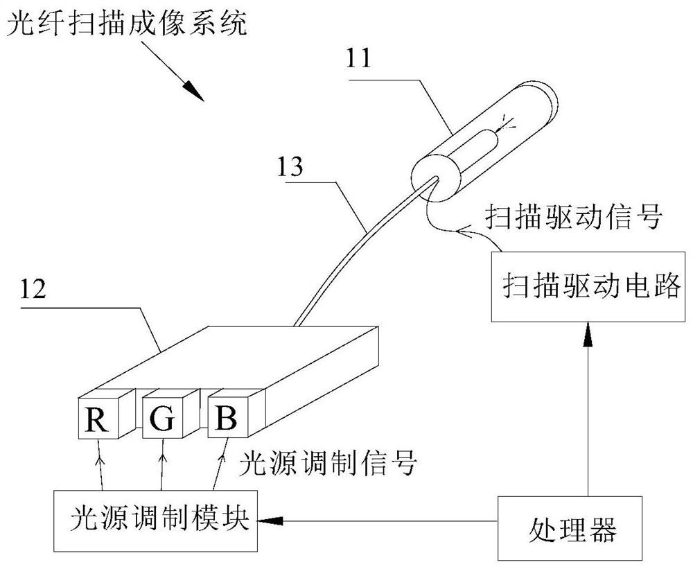
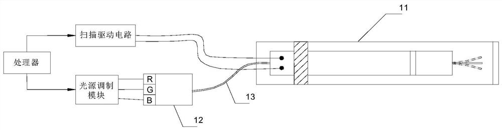
[0054] Please refer to Figure 1A and Figure 1B , Figure 1A and Figure 1B It is a schematic diagram of an optical fiber scanning imaging system provided by an embodiment of the present invention. The optical fiber scanning imaging system mainly includes: a processor, a scanning driving circuit, a light source module, a light source modulation module, a fiber optic scanner 11 , a light source combining module 12 and an optical fiber 13 . The working principle o...


PUM


Abstract

The invention discloses a near-eye display device and a projection feedback method, comprising an image light source and a feedback light source; an optical scanning device for scanning and emitting the display image light and the feedback image light; an optical waveguide; an image acquisition unit for Collect the feedback image light passing through the optical waveguide, and generate the collected image corresponding to the feedback image; a readable storage medium, the readable storage medium stores a program, and the following steps are implemented when the program is executed by the processor: Comparing the features of the preset object in the collected image with the features of the preset object in the standard projection image to obtain a comparison result, and adjusting the driving signal of the light scanning device based on the comparison result. The above solution is used to monitor the motion trajectory of the optical fiber in the optical fiber scanning imaging system, and then can provide a feedback signal for compensation control according to the motion trajectory of the optical fiber, thereby solving the technical problem of projection quality degradation.

Description

technical field [0001] The invention relates to the field of near-eye display, in particular to a near-eye display device and a projection feedback method. Background technique [0002] The imaging principle of fiber scanning display technology (fiber scanning display, FSD) is to drive the scanning fiber through the fiber scanner to move the predetermined two-dimensional scanning trajectory, and modulate the light output of the light source, that is, to modulate the image corresponding to each pixel of the image to be displayed. Then, the light corresponding to each pixel of the image to be displayed is projected onto the projection surface one by one through the scanning optical fiber, thereby forming a projection picture. [0003] As an image source, fiber optic scanners are easily affected by environmental factors such as temperature, humidity, vibration, driving fluctuations, and aging fatigue. , so that projection quality degradation occurs during long hours of work. ...

Claims


Application Information

Patent Timeline
Patent Type & Authority Patents(China)
IPC IPC(8): G02B27/01G02B26/10
CPCG02B26/103G02B26/106G02B27/0101
Inventor 宋海涛其他发明人请求不公开姓名
Owner CHENGDU IDEALSEE TECH
Why Eureka
Try Eureka