Optical fiber coupler, monitoring system and occupation state monitoring method

A technology of optical fiber coupler and occupancy state, which is applied in the direction of transmission monitoring/testing/fault measurement system, coupling of optical waveguide, transmission system, etc., and can solve problems such as low network troubleshooting efficiency, low speed of new business, and insufficient

Pending Publication Date: 2019-12-20
刘仁重
View PDF0 Cites 0 Cited by
  • Summary
  • Abstract
  • Description
  • Claims
  • Application Information

AI Technical Summary

Problems solved by technology

However, when the network maintenance personnel complete the service optical path according to the optical path business work order, due to individual differences among the network maintenance personnel, a large number of fiber jumping operations are not carried out according to the requirements on the business work order, which leads to the actual occupancy of the fiber coupler and the There is a huge gap in business work order data. According to the empirical data in the industry, the coincidence rate between business work order data and on-site occupancy is only 60%, and the network management department does not have sufficient human resources to discover this gap in time
This gap makes it impossible for operators to grasp the usage of network resources and make full use of existing network resources, resulting in a lot of waste of network resources; The efficiency of troubleshooting is low, the speed of opening new services is low, and the rate of user satisfaction is low
[0004] Therefore, when using business work order data to monitor the occupancy of each fiber coupler, it cannot reflect the real occupancy status of some fiber couplers
Therefore, the accuracy of the existing method to monitor the occupancy state of the fiber coupler is low

Method used


Image

  • Optical fiber coupler, monitoring system and occupation state monitoring method
  • Optical fiber coupler, monitoring system and occupation state monitoring method
  • Optical fiber coupler, monitoring system and occupation state monitoring method

Examples


Embodiment Construction

[0104] Exemplary embodiments of the present disclosure will be described in more detail below with reference to the accompanying drawings. Although exemplary embodiments of the present disclosure are shown in the drawings, it should be understood that the present disclosure may be embodied in various forms and should not be limited by the embodiments set forth herein. Rather, these embodiments are provided for more thorough understanding of the present disclosure and to fully convey the scope of the present disclosure to those skilled in the art.

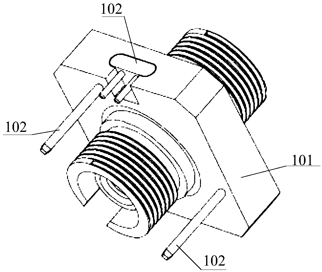
[0105] Such as figure 1 As shown, an embodiment of the present invention provides a fiber optic coupler, which includes:

[0106] A coupler body 101 and at least one occupancy monitoring element 102; the at least one occupancy monitoring element 102 is arranged in the coupler body 101;

[0107] Each of the occupancy monitoring elements 102 is used to monitor whether the coupler body 101 is in an occupancy state, and if so, send oc...


PUM


Abstract

The invention provides an optical fiber coupler, a monitoring system and an occupation state monitoring method. The optical fiber coupler comprises a coupler body and at least one occupation monitoring element, the at least one occupation monitoring element is arranged in the coupler body; each occupation monitoring element is used for monitoring whether the coupler body is in an occupation stateor not, and if yes, occupation state information is sent to an external monitoring device. Therefore, the scheme provided by the invention can improve the accuracy of monitoring the occupancy state ofthe optical fiber coupler.

Description

technical field [0001] The invention relates to the field of optical fiber technology, in particular to an optical fiber coupler, a monitoring system, and an occupation state monitoring method. Background technique [0002] With the development of communication technology, telecom operators' optical fiber networks are deployed more and more widely. Fiber is deployed segment by segment. Fiber couplers are usually used to connect these segmented optical fibers into service optical paths. Optical fiber network has the advantages of low cost and large bandwidth, but because the entire network is in a "passive" state except for the communication equipment at the initial end (A end) and end (Z end), it is called "dumb resource" in the industry. [0003] At present, network maintenance personnel usually perform fiber jumpers according to the optical path business order, and use fiber couplers and fiber jumpers to connect these segmented fibers into a complete service optical path...

Claims


Application Information

Patent Timeline
IPC IPC(8): H04B10/07H04B10/075G02B6/26
CPCG02B6/26H04B10/07H04B10/075
Inventor 刘仁重
Owner 刘仁重
Why Eureka
Try Eureka