Experimental device for acoustic metamaterial plate structure
A technology of acoustic metamaterials and experimental devices, applied in the direction of material analysis, measuring devices, and analytical materials using sound waves/ultrasonic waves/infrasonic waves, can solve problems that affect the accuracy of experimental data and lack of experimental devices, and achieve no prestress, Easy to operate and ensure the effect of accuracy
- Summary
- Abstract
- Description
- Claims
- Application Information
AI Technical Summary
Problems solved by technology
Method used
Image
Examples
specific Embodiment approach 1
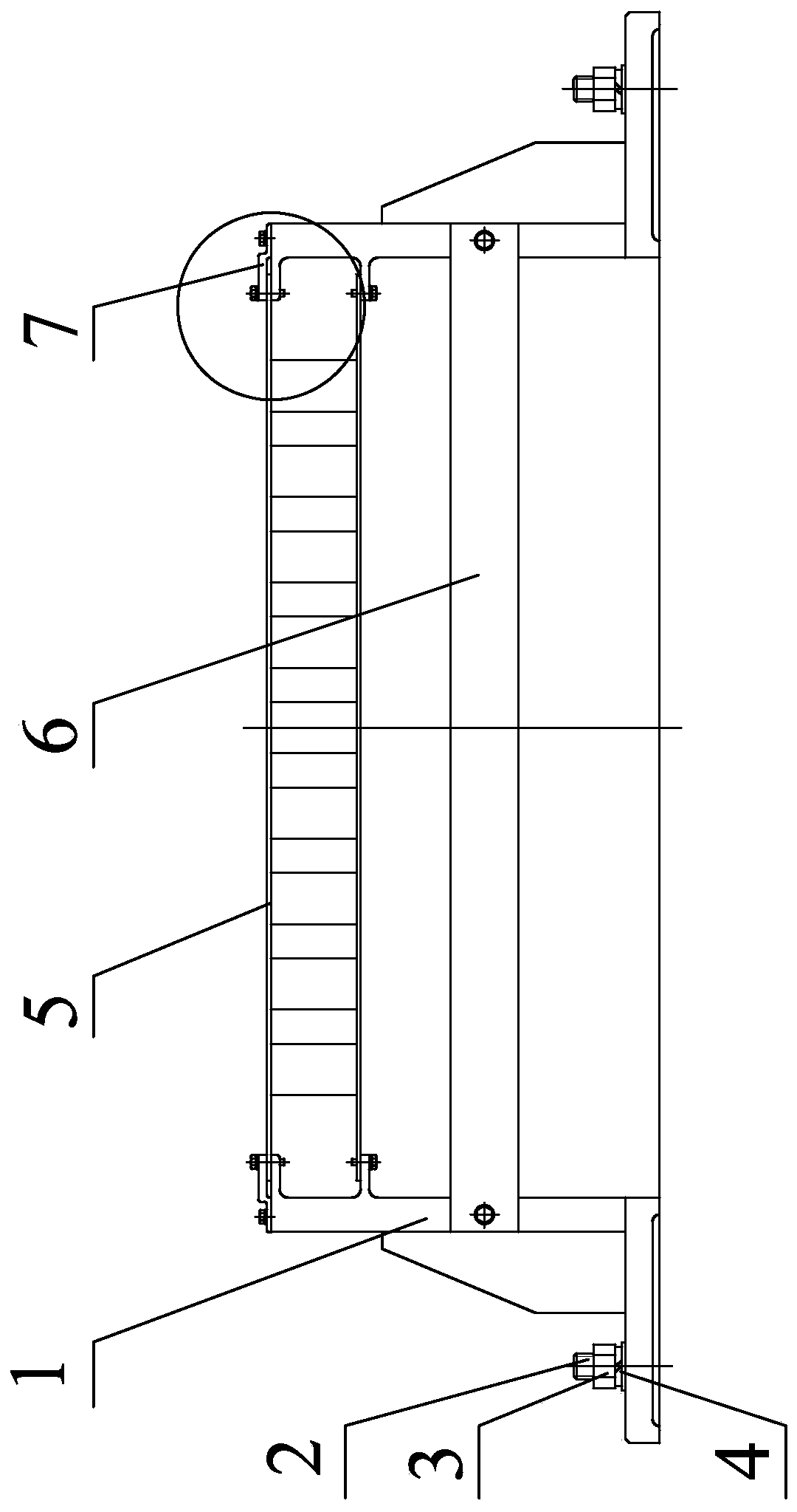
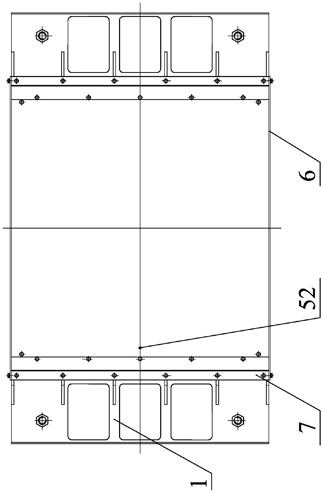
[0021] Specific implementation mode one: combine figure 1 with Figure 6 Describe this embodiment, an experimental device of an acoustic metamaterial plate structure in this embodiment, the experimental device includes a metamaterial plate 5, two clamp brackets 1, two positioning rods 6, two fixed pressure plates 7 and 2N connector, N is a positive integer;
[0022] The two clamp brackets 1 are relatively arranged on both sides of the metamaterial plate 5, and each fixed platen 7 is installed on the top of a clamp bracket 1, and a substrate 51 in the metamaterial plate 5 is arranged on the clamp bracket 1 and the fixed platen 7 between, and the metamaterial plate 5 is fixedly installed on the fixture bracket 1, each positioning rod 6 is arranged on one side of the two fixture brackets 1, and each positioning rod 6 is fixedly connected with the two fixture brackets 1, each The fixture bracket 1 is fixedly connected to the vibration-isolation foundation track through N connect...
specific Embodiment approach 2
[0024] Specific implementation mode two: combination Figure 6 with Figure 7 Describe this embodiment, this embodiment is to further limit the metamaterial plate 5 described in the first embodiment, in this embodiment, the metamaterial plate 5 includes two substrates 51 and Z straight rods 53, Z is Positive integer, two substrates 51 are arranged in parallel, Z straight rods 53 are evenly distributed between the two substrates 51, and one end of each straight rod 53 is fixedly connected to a substrate 51, and the upper surface of each substrate 51 is provided with several A vibration hole 52. Other compositions and connection methods are the same as those in Embodiment 1.
[0025] In this embodiment, the metamaterial plate 5 includes two substrates 51, one of which is arranged between the fixture bracket 1 and the fixed platen 7 for clamping and fixing, and the other substrate 51 is installed on the fixture bracket 1 to realize Double fixation ensures a more stable install...
specific Embodiment approach 3
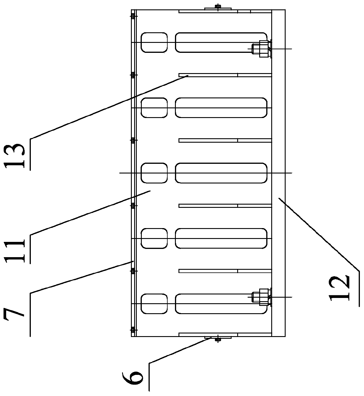
[0026] Specific implementation mode three: combination Figure 3 to Figure 5 Describe this embodiment, this embodiment is to further limit the clamp bracket 1 described in the first embodiment, in this embodiment, the clamp bracket 1 includes a vertical plate 11 and a bottom plate 12, and the bottom surface of the vertical plate 11 is fixed on On the upper surface of the bottom plate 12, N through holes 121 are arranged on the end of the top surface of the bottom plate 12 away from the vertical plate 11, and each connector is arranged in a through hole 121, and the top surface of the vertical plate 11 is equidistantly arranged along the length direction. M threaded blind holes, M is a positive integer, the side of the vertical plate 11 away from the bottom plate 12 is provided with a connecting square bar 111, and the connecting square bar 111 is provided with a connecting groove 112, and another base plate 51 in the metamaterial plate 5 is arranged on the connection slot 112....
PUM
 Abstract
Description
Claims
Application Information
 - R&D
- Intellectual Property
- Life Sciences
- Materials
- Tech Scout
- Unparalleled Data Quality
- Higher Quality Content
- 60% Fewer Hallucinations
Browse by: Latest US Patents, China's latest patents, Technical Efficacy Thesaurus, Application Domain, Technology Topic, Popular Technical Reports.
© 2025 PatSnap. All rights reserved.Legal|Privacy policy|Modern Slavery Act Transparency Statement|Sitemap|About US| Contact US: help@patsnap.com


