
An oil mist collector for a precision machining plant

A technology of precision machinery and processing plants, applied in the field of oil mist collection equipment, can solve the problems of increasing oil mist viscosity, affecting oil mist collection rate, working environment pollution, etc., and achieve the effect of increasing oil collection speed

Active Publication Date: 2020-07-14
YANTAI FRIED ROBOT CO LTD
View PDF6 Cites 0 Cited by
  • Summary
  • Abstract
  • Description
  • Claims
  • Application Information

AI Technical Summary

Problems solved by technology

[0003] The oil mist generated during the processing will cause great pollution to the working environment and pose a greater threat to the health of the staff. Therefore, the collection of oil mist is very necessary. The existing oil mist collection devices are usually made of The impeller of the motor rotates to form a negative pressure, and 1-3 layers of filters are set to filter the oil, and the oil is flowed down by gravity to complete the collection of the oil mist, but the oil mist generated during the processing often contains metal powder generated by cutting, which will increase The viscosity of the oil mist is not easy to flow down from the filter screen, and the filter screen will be blocked, which will affect the collection rate of oil mist

Method used


Image

  • An oil mist collector for a precision machining plant
  • An oil mist collector for a precision machining plant
  • An oil mist collector for a precision machining plant

Examples


Embodiment Construction

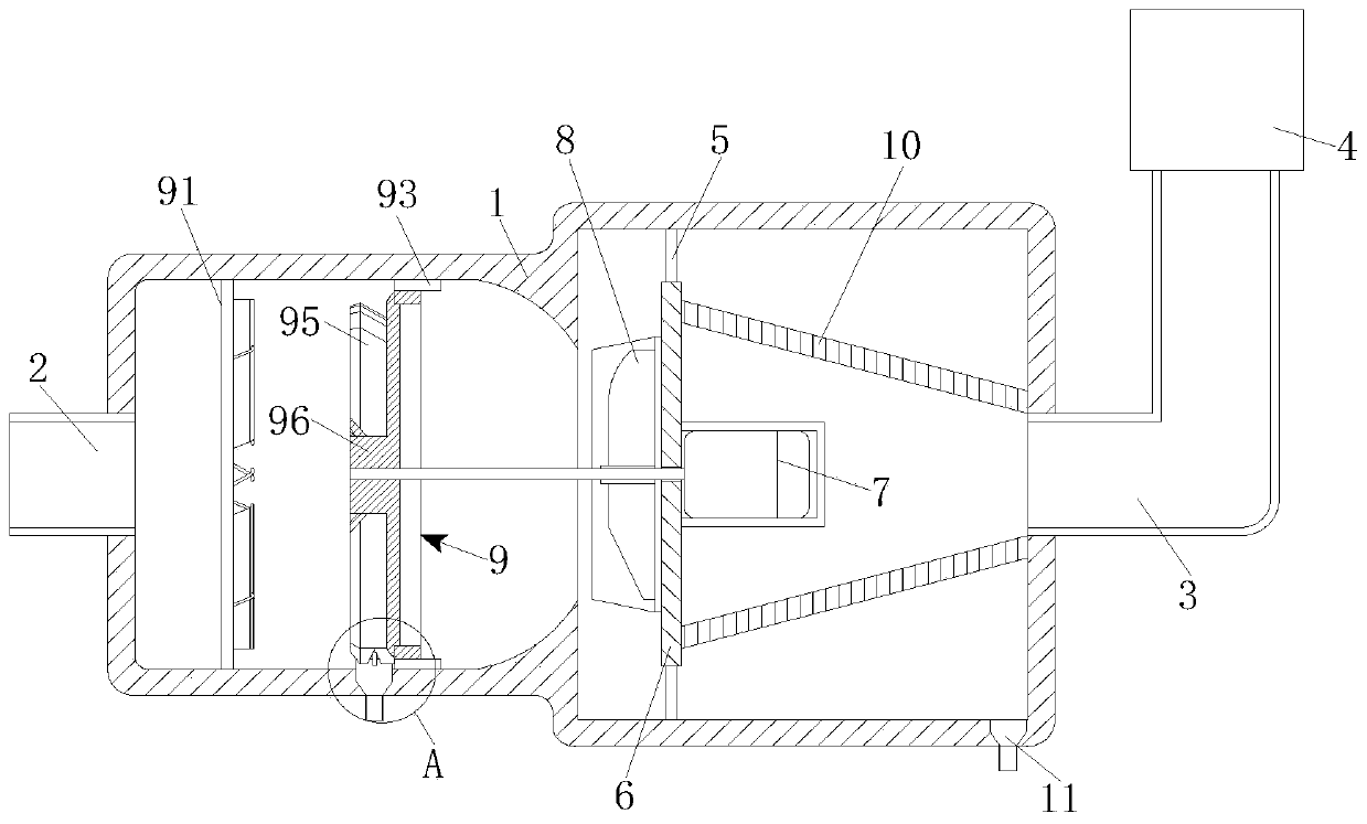
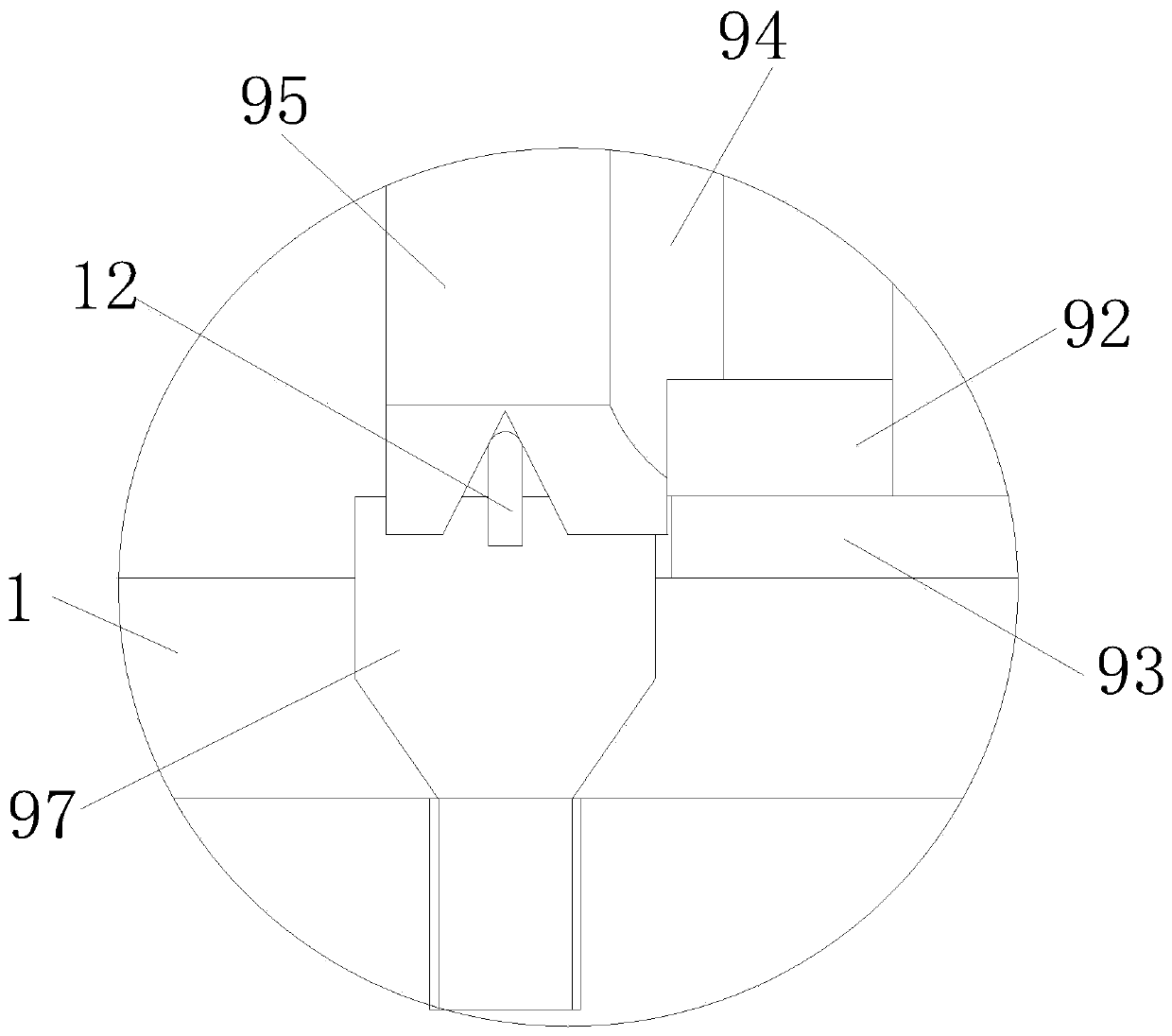
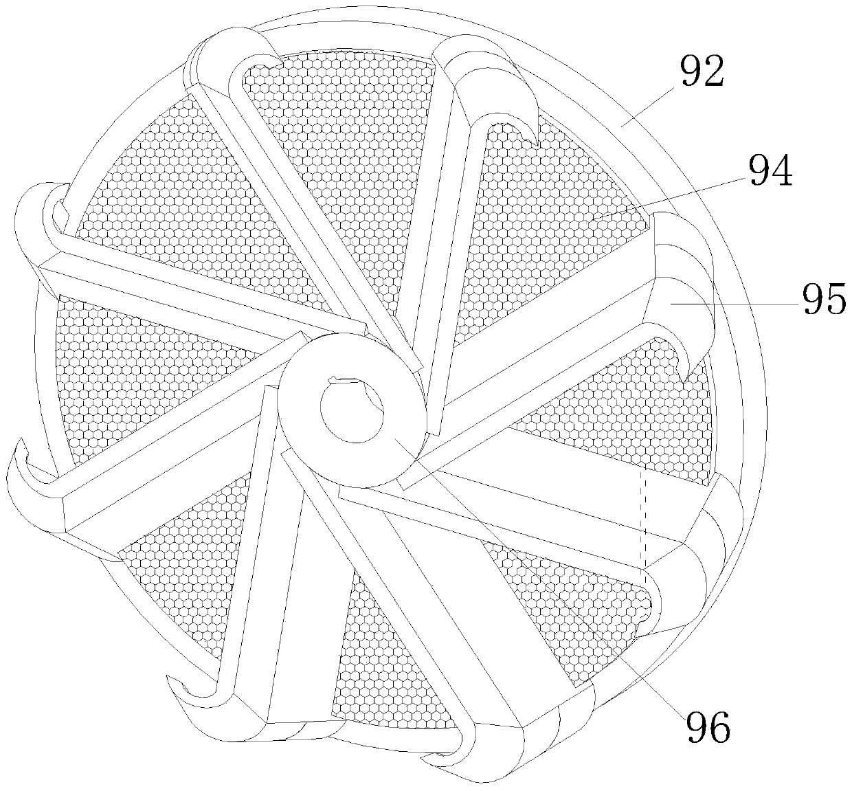
[0021] see Figure 1-4 , the present invention provides a technical solution: an oil mist collector for precision machinery processing plants, including a casing 1, the left half of the casing 1 is cylindrical, and the left and right sides of the casing 1 are respectively provided with suction pipes 2 and the air outlet pipe 3, the position of the air outlet pipe 3 is connected with the inlet of the HEPA filter 4, the inner wall of the casing 1 is fixedly connected with the side wall of the installation plate 6 through the connecting rod 5, the installation disk 6 and the left and right sides of the casing 1 The sides are parallel, a motor 7 is fixedly installed on the right side of the mounting plate 6, the output shaft of the motor 7 runs through the mounting plate 6 to its left side and is fixedly sleeved with an impeller 8, and the left half of the casing 1 is provided with a primary filter mechanism 9, installed The right side of the disc 6 and the outer side of the motor...


PUM


Abstract

The invention belongs to the technical field of oil mist collection equipment and discloses an oil mist collector for precision machinery processing plants. The oil mist collector for precision machinery processing plants includes a casing. The left half of the casing is cylindrical, and the left and right sides of the casing are respectively provided with a suction pipe and an air outlet pipe. The position is connected with the entrance of the HEPA filter, the inner wall of the casing is fixedly connected with the side wall of the installation plate through the connecting rod, the installation plate is parallel to the left and right sides of the casing, the motor is fixedly installed on the right side of the installation plate, and the motor output shaft runs The left side of the mounting plate is fixedly sleeved with an impeller, the left half of the casing is provided with a primary filter mechanism, and the right side of the mounting plate is fixedly connected to the left end face of the filter cartridge outside the motor. The oil mist collector for precision machinery processing plants can greatly increase the oil collection speed through the improvement of the primary filter mechanism, and can avoid the problem of affecting the oil collection efficiency due to the blockage of the primary filter screen.

Description

technical field [0001] The invention relates to the technical field of oil mist collection equipment, in particular to an oil mist collector for precision machinery processing plants. Background technique [0002] The processing of precision parts by machine tools often involves cutting processing. The formation of metal cutting fluid oil mist during processing can be mainly attributed to two mechanisms, atomization and evaporation: atomization is the process of converting mechanical energy into droplet surface energy. Mainly due to the violent impact of the liquid on the fixed and rotating units in the machine tool system, it is broken by it, forming fine droplets floating in the working environment; evaporation occurs because a large amount of heat is generated in the cutting area, and the heat is transmitted to the cutting fluid to make it Its temperature is significantly higher than the saturation temperature, and boiling occurs on the solid-liquid contact surface and st...

Claims


Application Information

Patent Timeline
Patent Type & Authority Patents(China)
IPC IPC(8): B01D50/00
CPCB01D50/20
Inventor 苏峰王虹
Owner YANTAI FRIED ROBOT CO LTD
Learn More