Supercharge Your Innovation With Domain-Expert AI Agents!

Compact integrated multi-group separated magnetic encoder

A magnetic encoder, a compact technology, applied in the direction of instruments, converting sensor outputs, and using electromagnetic/magnetic devices to transmit sensing components, etc., can solve problems such as a lot of available space, the length of joints cannot be reached to the limit, and the length of joints is affected.

Pending Publication Date: 2019-12-31
北京金钢科技有限公司
View PDF10 Cites 0 Cited by
  • Summary
  • Abstract
  • Description
  • Claims
  • Application Information

AI Technical Summary

Problems solved by technology

However, general robot joints have more available space in the radial direction, and the axial size directly affects the overall length of the joint. The dual-encoder structure proposed in this patent still has a certain surplus in radial space, and the axial distribution of the dual-encoders The joint length cannot be reached to the extreme, and there is still room for optimization and improvement
[0008] The hollow encoder is different from the shaft end encoder. The hollow encoder must have a unique structure to achieve anti-interference and achieve high precision, high resolution, and magnetic interference resistance. Patent 2019108505346 proposes a method to protect the above-mentioned separate The structural scheme of the magnetic encoder, but this structure is limited to the application of a single encoder. If it is to achieve multiple encoders, the structure needs to be further optimized

Method used


Image

  • Compact integrated multi-group separated magnetic encoder
  • Compact integrated multi-group separated magnetic encoder

Examples


Embodiment Construction

[0023] Embodiments of the patent of the present invention are described with reference to the accompanying drawings.

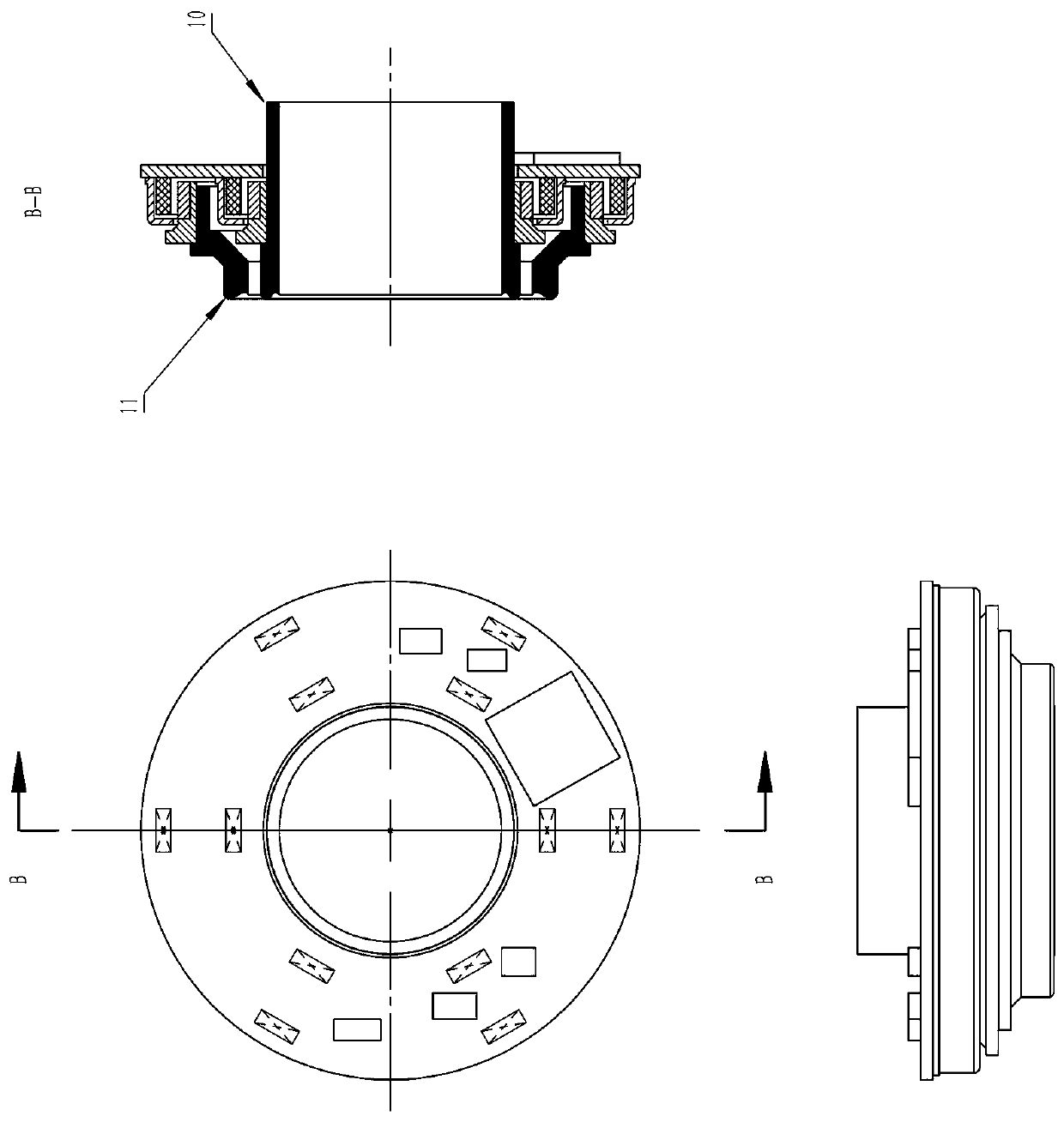
[0024] see figure 1 , figure 1 The compact all-in-one multi-group discrete magnetic encoder has two encoder configurations. The circuit board 1 is used as a shared component of two groups of configurations, and the static parts (magnetic sensitive element 3 , shielding case 6 and shielding case 9 ) of the two groups of encoders are welded on the left side of the circuit board 1 .

[0025] The chip 2 is welded on the circuit board 1. In order to save the radial space, it can be welded on the right side of the circuit board 1. If the axial space needs to be saved, the radial dimension of the circuit board 1 in the figure needs to be expanded and soldered On the radial expansion space on the left side of the circuit board 1.

[0026] The shield 9 and the magnetic sensitive element 3 therein together form the static part of the encoder set 1 ; the shield 6 and ...


PUM


Abstract

A compact integrated multi-group separated magnetic encoder of the invention is characterized in that: an encoder with adjustable group number, which is formed by a group or multi-group separated magnetic encoder principles and a hollow magnetic shielding encoder structure, is adopted, and the group number of the encoder can be expanded in a radial space, extremely compact space occupation is achieved while stable output among all groups of encoders can be ensured, thus excellent size can be provided for application scenes with high space requirements, and at the same time, position data withhigh precision and high resolution can be output.

Description

technical field [0001] The patent of the present invention relates to a device for position measurement, especially an encoder device for rotary position measurement. Background technique [0002] When the object rotates, in order to measure the position and motion state of the moving object, an encoder is generally used for measurement. The encoder returns the rotation law and data of the current object, which is provided to the system for analysis and subsequent control. [0003] In principle, encoders have the following categories: photoelectric encoders, magnetic encoders, capacitive encoders, inductive encoders, resolvers, etc.; in terms of structure, they can be divided into two types: shaft end encoders and hollow encoders. [0004] As an emerging technology, magnetic encoders are used more and more in the market, and their excellent anti-interference ability and stability are more and more favored by more products. Moreover, with the continuous growth of semiconduc...

Claims


Application Information

Patent Timeline
IPC IPC(8): G01D5/244G01D5/245
CPCG01D5/24423G01D5/245
Inventor 梁正
Owner 北京金钢科技有限公司
Features
  • R&D
  • Intellectual Property
  • Life Sciences
  • Materials
  • Tech Scout
  • Unparalleled Data Quality
  • Higher Quality Content
  • 60% Fewer Hallucinations
Learn More