

Glass machining device and method
A processing device and glass technology, applied in the direction of stone processing tools, stone processing equipment, work accessories, etc., can solve the problems of glass scribing and breaking that cannot be different in size
- Summary
- Abstract
- Description
- Claims
- Application Information
AI Technical Summary
Problems solved by technology
Method used
Image

Examples
specific Embodiment approach 1
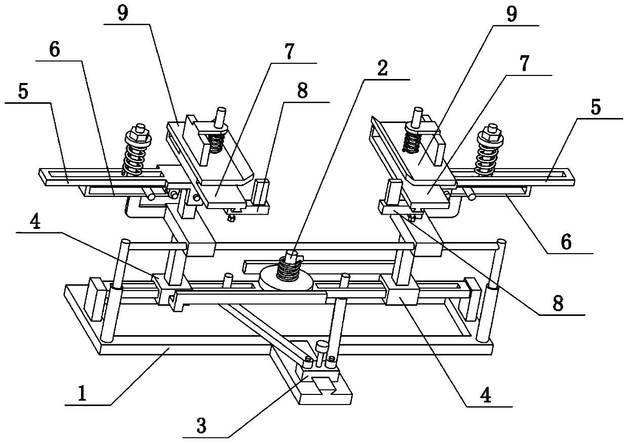
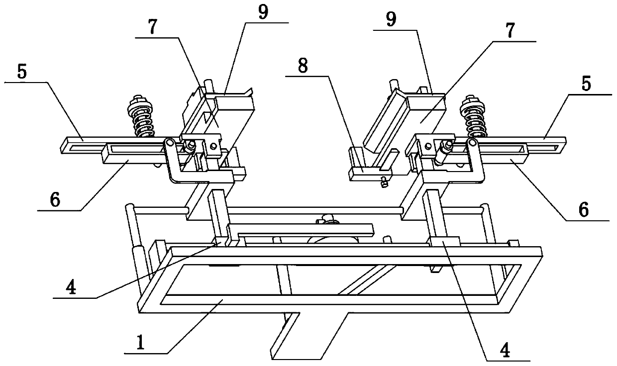
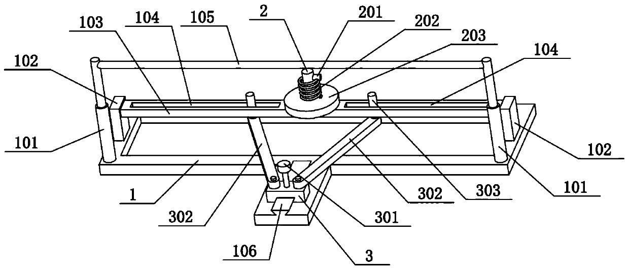
[0034] Combine below Figure 1-10 Describe this embodiment, the present invention relates to the field of glass processing, more specifically a glass processing device, including a rectangular bottom frame 1, a convex plate 102, a beam rod 103, a sliding sleeve 4, a vertical pillar 403, a rotating plate 5, a lower Clamping plate 7, top seat 703, riser 704, upper clamping plate 9, spring sleeve column 901 and compression spring II902, the present invention can break off after the glass of different sizes is scored.
[0035]The left and right ends of the rectangular bottom frame 1 are fixedly connected with convex plates 102, and a beam rod 103 is fixedly connected between the two convex plates 102. On the crossbeam rod 103, the upper ends of the two sliding sleeves 4 are fixedly connected with vertical struts 403, the upper ends of the two vertical struts 403 are hingedly connected with the rotating plate 5, and the upper ends of the two rotating plates 5 are fixedly connected ...
specific Embodiment approach 2
[0037] Combine below Figure 1-10 To illustrate this embodiment, the glass processing device further includes a fixed shaft 2, a fixed pin 201, a torsion spring 202, a gear 203, and a rack 401. Gear 203, the upper end of fixed shaft 2 is fixedly connected with fixed pin 201, one end of torsion spring 202 is fixedly connected on fixed pin 201, the other end of torsion spring 202 is fixedly connected on gear 203, and both sliding sleeves 4 are fixedly connected There are racks 401, and two racks 401 are respectively engaged with the front and rear sides of the gear 203 for transmission. The torsion spring 202 gives the gear 203 torque, so that the gear 203 always has a tendency to rotate counterclockwise. When the gear 203 rotates counterclockwise, it drives the two racks 401 to approach each other, and finally drives the two sliding sleeves 4 to approach each other, so that the two vertical pillars 403 There is always a tendency to approach each other, so that the left and rig...
specific Embodiment approach 3
[0039] Combine below Figure 1-10 To illustrate this embodiment, the glass processing device also includes a rectangular sliding hole 104, a trapezoidal slide rail 1106, a slider 3, a fastening screw 1301, an equal arm 302 and a convex cylinder 303, and the left and right ends of the beam bar 103 are provided with Rectangular sliding hole 104, the front middle part of rectangular bottom frame 1 is fixedly connected with trapezoidal slide rail 1106, is slidably connected with slide block 3 on the trapezoidal slide rail 1106, and the left and right ends of slide block 3 are all hingedly connected with equal arm bar 302, two The other ends of each equal arm 302 are fixedly connected with convex cylinders 303, and the two convex cylinders 303 are respectively slidably connected to the two rectangular sliding holes 104, and the two convex cylinders 303 are located between the two sliding sleeves 4. 3 is threadedly connected with a fastening screw I301, and the fastening screw I301 ...
PUM
 Abstract
Description
Claims
Application Information