Lifting control device for vehicle release

A lift control and vehicle technology, applied in the direction of restricting traffic, roads, road signs, etc., can solve the problems of inability to adapt and ensure road public safety, etc.

Inactive Publication Date: 2020-02-04
武汉鑫艺驰道路设施有限公司
View PDF6 Cites 0 Cited by
  • Summary
  • Abstract
  • Description
  • Claims
  • Application Information

AI Technical Summary

Problems solved by technology

[0005] The technical problem to be solved by the present invention is that there is a technical problem that the restricted height ca

Method used


Image

  • Lifting control device for vehicle release
  • Lifting control device for vehicle release
  • Lifting control device for vehicle release

Examples


Embodiment Construction

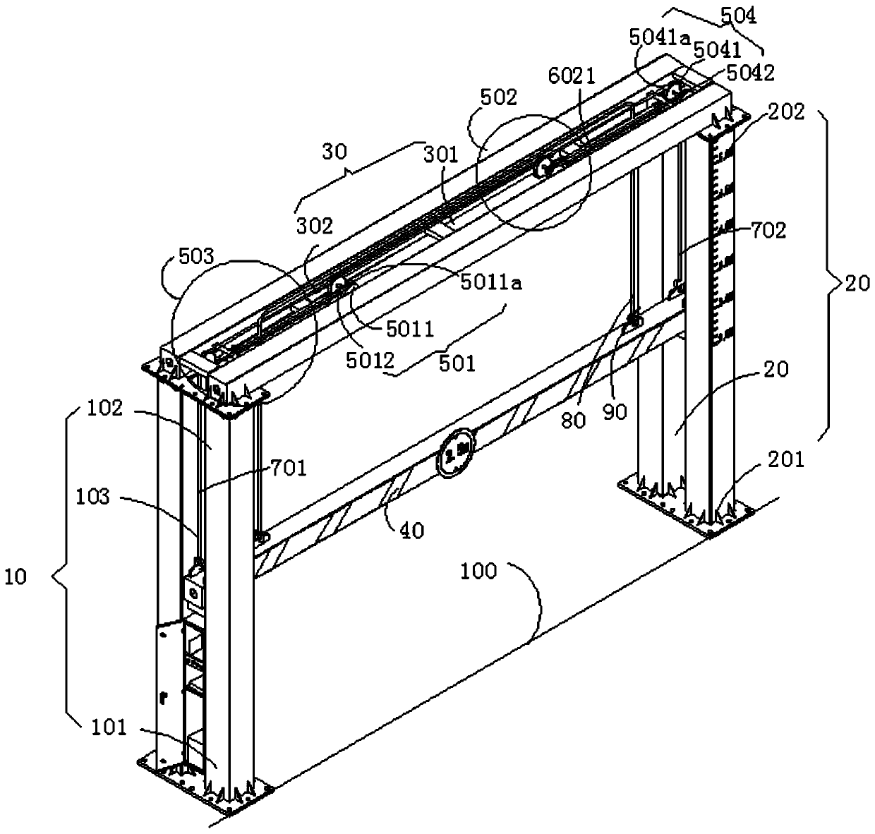
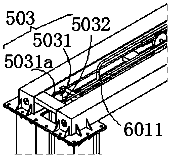
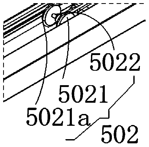
[0040] see Figure 1-10 , the present invention discloses a lifting control device for vehicle release, by fixing the first installation end 101 of the left installation column 10 and the third installation end 201 of the right installation column 20 to the ground 100 respectively, the two ends of the top beam 30 The ends are respectively fixedly connected with the second installation end 102 of the left installation post 10 and the fourth installation end 202 of the right installation post 20 . At the same time, the two ends of the release rod 40 are respectively slidably arranged inside the first lifting area 103 of the left mounting column 10 and the inside of the second lifting area 203 of the right mounting column 20, so that the release rod 40 passes through the first The lifting area 103 and the second lifting area 203 can slide relative to the left mounting column 10 and the right mounting column 20 at the same time. Each group of sliding mechanisms is arranged inside...


PUM


Abstract

The invention discloses a lifting control device for vehicle release, and belongs to the technical field of traffic equipment. The lifting control device comprises a left mounting column, a right mounting column, a top beam, a release rod, a plurality of sliding mechanisms, lifting mechanisms and two pull rope chains, wherein the number of the lifting mechanisms is the same as that of the slidingmechanisms; a transverse sliding groove is formed between the two ends of the top beam, and a sliding rail is fixed in the transverse sliding groove; the plurality of sliding mechanisms are arranged in the transverse sliding groove and are connected with the sliding rail correspondingly arranged in the transverse sliding groove by bearings; each lifting mechanism is arranged in the transverse sliding groove, and is connected with the corresponding sliding mechanism arranged in the transverse sliding groove; one end of each pull rope chain is fixedly connected with the release rod, and the other end winds around the corresponding sliding mechanism and lifting mechanism to be fixedly connected with the transverse sliding groove, so that the sliding mechanisms are pushed by the lifting mechanisms to drive the pull rope chains to move in the transverse sliding groove. The device achieves the technical effect of timely adjusting limiting height according to demands of non-restricted vehicles and ensuring public safety of roads.

Description

technical field [0001] The invention belongs to the technical field of traffic equipment, in particular to a lifting control device for vehicle release. Background technique [0002] The height-limited gate refers to the door-type height-limited structure set up to protect bridges, culverts, and tunnels on the road. When the height is high, if the vehicle continues to drive, it is easy to cause a road traffic safety accident of collision. [0003] For the technology applied to traffic equipment, the highway height limit equipment is mainly composed of a door-type steel structure, a height limit sign, and a flashing warning signal light. The two pillars of the door-type steel structure are fixed on the road, and then the door The top steel beam of the type steel structure is welded to the pillars on both sides to restrict the passage of vehicles whose height is higher than the top steel beam, and allow the passage of vehicles whose height is lower than the top steel beam. H...

Claims


Application Information

Patent Timeline
IPC IPC(8): E01F13/00E01F13/04E01F9/608
CPCE01F13/00E01F13/04E01F9/608
Inventor 祖光浩祖光容
Owner 武汉鑫艺驰道路设施有限公司
Why Eureka
Try Eureka