Display control circuit and device

A display control and circuit technology, applied in static indicators, instruments, etc., can solve the problem of high cost

Pending Publication Date: 2020-02-07
GREE ELECTRIC APPLIANCES INC
View PDF0 Cites 0 Cited by
  • Summary
  • Abstract
  • Description
  • Claims
  • Application Information

AI Technical Summary

Problems solved by technology

[0003] Based on this, it is necessary to use MCU to control the display control circuit in the controller of traditional household appliances, which leads to high cost technical problems, and provide a cost-reducing method that does not require the use of MCU and uses pure hardware to control and display the product status. The display control circuit and equipment

Method used


Image

  • Display control circuit and device
  • Display control circuit and device

Examples


Embodiment Construction

[0017] In order to make the purpose, technical solution and advantages of the present application clearer, the present application will be further described in detail below in conjunction with the accompanying drawings and embodiments. It should be understood that the specific embodiments described here are only used to explain the present application, and are not intended to limit the present application.

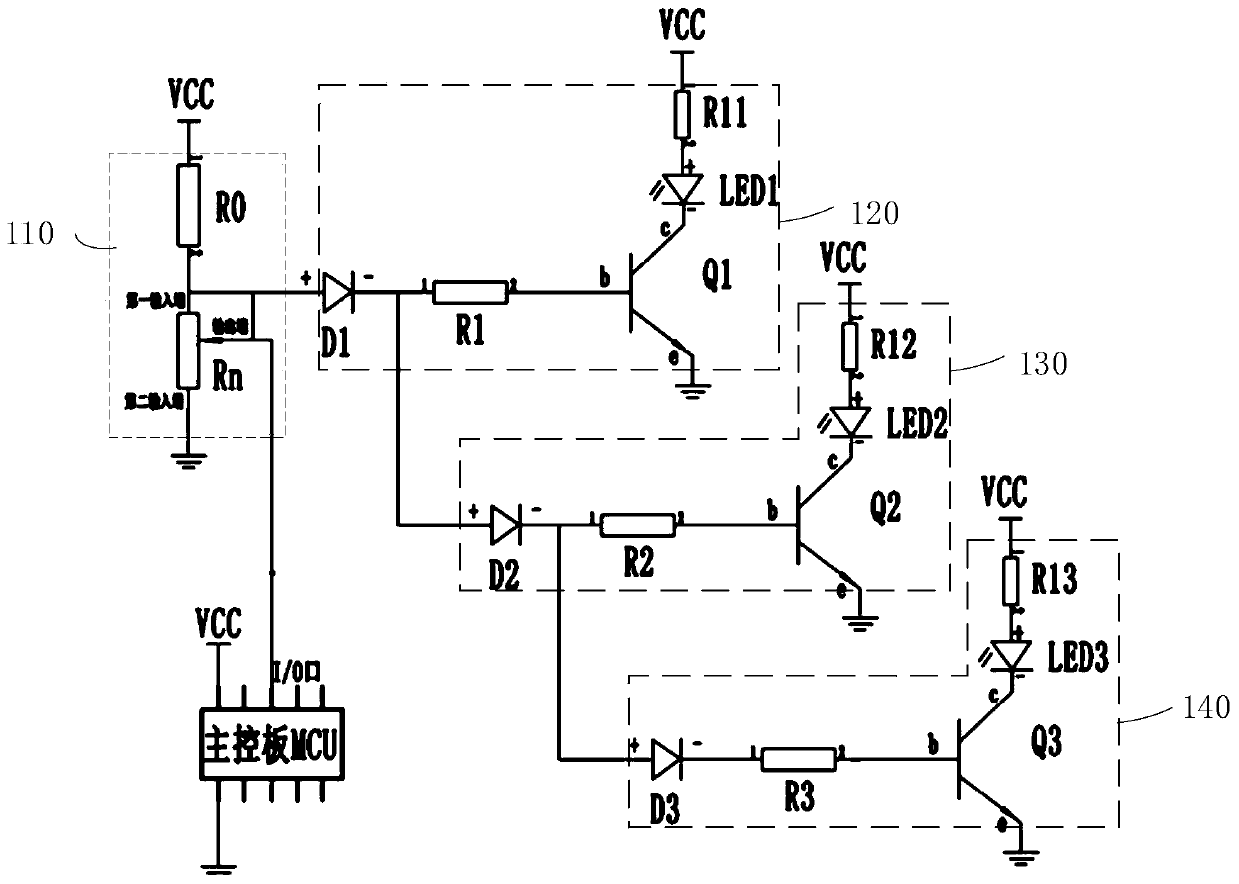
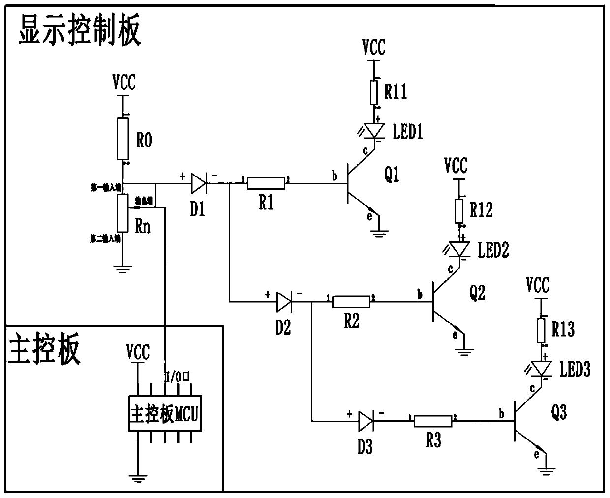
[0018] In one embodiment, such as figure 1 As shown, a display control circuit includes a resistance adjustment component 110 and at least two light emitting units, the first end of the resistance adjustment component 110 is connected to an external power supply port, the second end of the resistance adjustment component 110 is grounded, and each light emitting unit includes a switch The control end of the switch tube is connected to the output end of the resistance adjustment component 110, the first end of the switch tube is grounded, the second end of the switch tube is...


PUM


Abstract

The invention relates to a display control circuit and device. The display control circuit comprises a resistance adjusting assembly and at least two light-emitting units, wherein the first end of theresistance adjusting assembly is connected to an external power supply port; the second end of the resistance adjusting assembly is grounded; each light-emitting unit comprises a switch tube and a light-emitting assembly; the control end of the switch tube is connected with the output end of the resistance adjusting assembly; the first end of the switch tube is grounded; the second end of the switch tube is connected with the negative electrode of the light-emitting assembly, and the positive electrode of the light-emitting assembly is connected into an external power port; the light-emittingunit is used for indicating the working state of the electric appliance; the resistance value of the switch tube connected to the display control circuit is adjusted through the resistance adjustingassembly, so that the voltage is adjusted, and the conduction of the switch tube of the light emitting unit can be controlled; the light emitting assembly is controlled to emit light to indicate the working state of an electric appliance; and the display control device can realize display control through pure hardware without adding an MCU, and the cost can be reduced.

Description

technical field [0001] The present application relates to the technical field of display control, in particular to a display control circuit and equipment. Background technique [0002] At present, the controllers of household appliances are mostly a main control board and a display control board. The main control board and the display board each have at least one MCU. The communication method is used to transmit information to control the good work of the electrical appliances, which can reduce the distance between the two control boards. The number of connections between them to reduce costs and enhance anti-interference ability. The MCU on the main control board controls the working status of the product, including various load work and load status detection functions; the MCU on the display control board is electrically connected to the MCU on the main control board to communicate, exchange status information, and display the control board at the same time The MCU on th...

Claims


Application Information

Patent Timeline
Patent Type & Authority Applications(China)
IPC IPC(8): G09G3/32
CPCG09G3/32
Inventor 朱永哲陈定武贺凯曹文亮
Owner GREE ELECTRIC APPLIANCES INC
Why Eureka
Try Eureka