Check patentability & draft patents in minutes with Patsnap Eureka AI!

Scraping mechanism of centrifugal machine

A centrifuge and scraper technology, applied in centrifuges and other directions, can solve the problems of complex steps, low efficiency, and non-compliance with GMP requirements, and achieve the effects of simplifying operating steps, rapid stirring, and reducing costs

Pending Publication Date: 2020-02-21
蚌埠精工制药机械有限公司
View PDF0 Cites 3 Cited by
  • Summary
  • Abstract
  • Description
  • Claims
  • Application Information

AI Technical Summary

Problems solved by technology

[0003] This traditional method is not only laborious but also inefficient by manually scraping materials. In addition, due to the need to transfer solid-phase materials between two containers, the steps are more complicated and inefficient, and bacteria and impurities are easily mixed in during the transfer process, which does not meet the requirements GMP requirements

Method used


Image

  • Scraping mechanism of centrifugal machine
  • Scraping mechanism of centrifugal machine
  • Scraping mechanism of centrifugal machine

Examples


Embodiment Construction

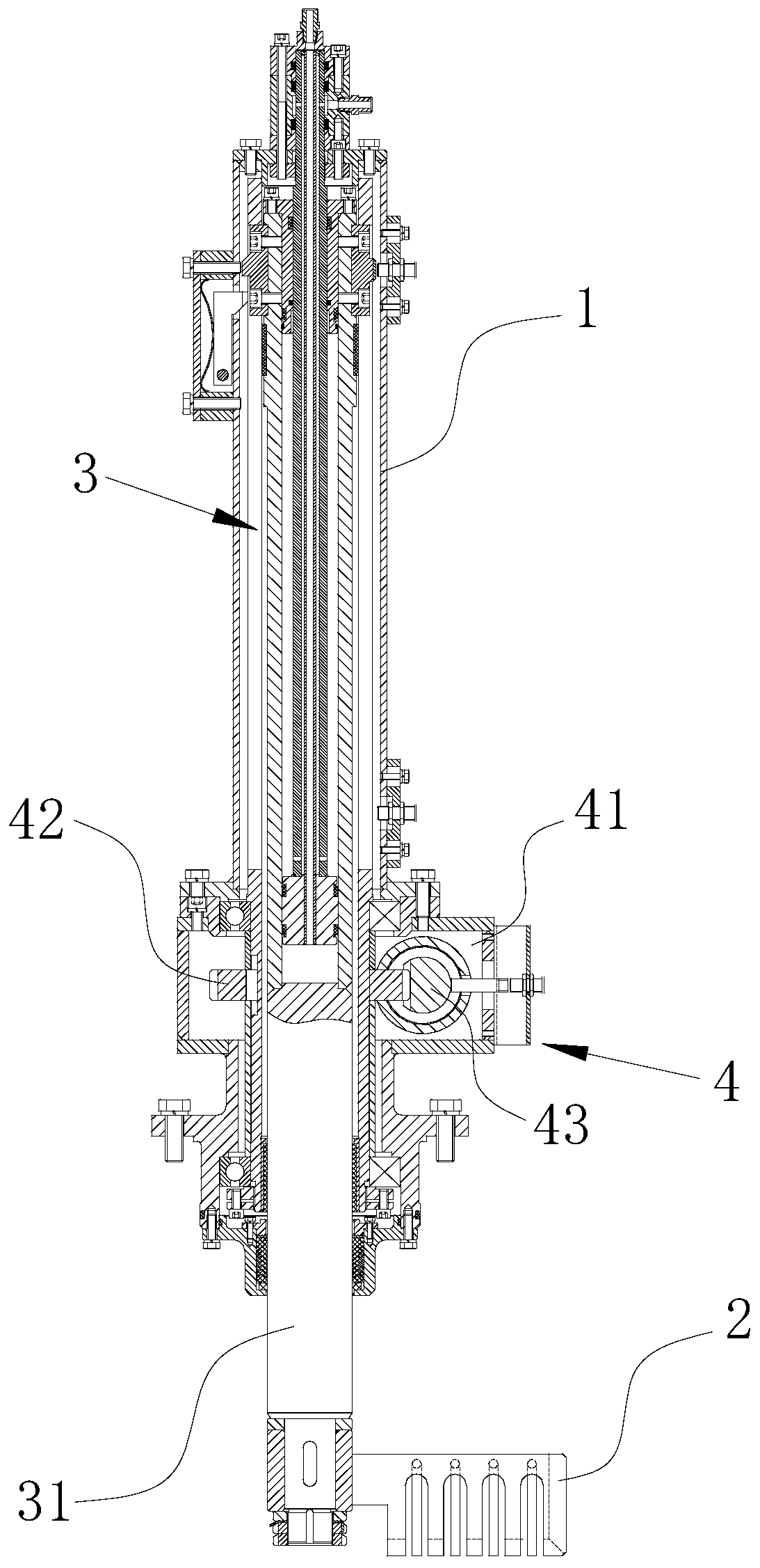
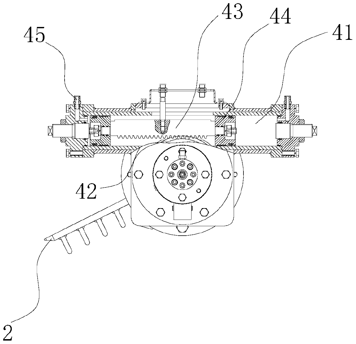
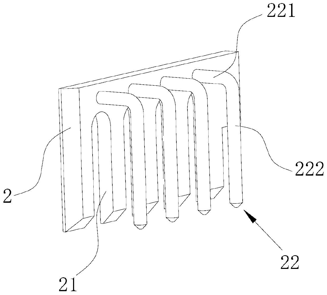
[0021] see Figure 1-Figure 5 , a centrifuge scraping mechanism, including a casing 1, a scraper plate 2 and a scraper shaft; the scraper shaft is arranged in the casing 1, the middle part of the casing 1 is fixedly connected with the centrifuge upper cover 6, and extends vertically from the lower side of the casing 1 and extends into the drum 5; the scraper 2 at the lower end of the scraper shaft is a rectangular plate arranged vertically, one side of the length direction of the scraper 2 is connected to the lower part of the scraper shaft, and the lower side of the scraper 2 is provided with several The slots 21 are arranged at intervals in the length direction, and an L-shaped bar 22 is provided above each slot 21 on one side of the scraper 2 in the thickness direction. The L-shaped bar 22 is formed by a horizontal part 221 Formed with the vertical part 222, the horizontal part 221 is connected to the scraper 2 along the side away from the vertical part 222 along its length...


PUM


Abstract

The invention discloses a scraping mechanism of a centrifugal machine. The scraping mechanism comprises a scraping plate and a scraping knife shaft, wherein the scraping plate is a vertically arrangedrectangular plate; one side, in the length direction, of the scraping plate is connected to the lower part of the scraping knife shaft; the lower side of the scraping plate is provided with a plurality of through slots which are formed in a spaced mode in a length direction of the scraping plate; an L-shaped rod is arranged on a position, above each through slot, at one side in the thickness direction of the scraping plate, and the L-shaped rod is composed of a horizontal part and a vertical part which are connected end to end, one side, away from the vertical part, in the length direction ofthe horizontal part is connected to the scraping plate, one side, away from the horizontal part, in the length direction of the vertical part vertically downwards extends, and the lower side of the vertical part is flush to the lower side of the scraping plate. The scraping mechanism can automatically perform scraping operation after centrifugal operation is accomplished; moreover, after scrapingis accomplished, solid-phase materials are directly crushed, stirred and dissolved in a rotary drum, and the materials do not need to transfer, so that operation steps can be simplified, efficiency is improved, and cost is reduced.

Description

technical field [0001] The invention relates to a centrifuge scraping mechanism. Background technique [0002] After centrifugation in the field of pharmaceutical processing, the liquid phase will be extracted by the liquid pumping device, and the remaining solid phase materials will stick to the inner wall of the centrifuge drum. Now there is generally a scraping step. The scraping step is to use Manually scrape the solid phase material from the inner wall of the drum into the drum, then transfer it to other containers to add solvent, and manually crush and stir to dissolve it. The obtained solution can be used for other purposes or subsequent processing. [0003] This traditional method is not only laborious but also inefficient by manual scraping. In addition, due to the need to transfer the solid-phase material between two containers, the steps are more complicated and the efficiency is not high, and bacteria and impurities are easily mixed during the transfer process, w...

Claims


Application Information

Patent Timeline
Patent Type & Authority Applications(China)
IPC IPC(8): B04B11/08B04B15/06
CPCB04B11/08B04B15/06
Inventor 金奕彤金波
Owner 蚌埠精工制药机械有限公司
Features
  • R&D
  • Intellectual Property
  • Life Sciences
  • Materials
  • Tech Scout
  • Unparalleled Data Quality
  • Higher Quality Content
  • 60% Fewer Hallucinations
Learn More