Electroencephalogram signal acquisition device and method

An EEG signal and collection device technology, applied in the field of EEG signals, can solve the problems of unsatisfactory EEG signal processing results, poor EEG signal measurement accuracy, and inconsistent contact of electrode pads, so as to ensure the accuracy of collection and avoid problems such as Errors, reducing the effect of circuit structure

Active Publication Date: 2020-02-28
深圳市杰纳瑞医疗仪器股份有限公司
View PDF11 Cites 3 Cited by
  • Summary
  • Abstract
  • Description
  • Claims
  • Application Information

AI Technical Summary

Problems solved by technology

[0004] Most of the existing EEG signal acquisition devices adopt a ring structure, which has poor adaptability to different head shapes. At the same time, the electrodes are not in close contact with the skin, which makes the measurement accuracy of EEG signals poor, and the subsequent EEG signal processing results are not ideal.

Method used


Image

  • Electroencephalogram signal acquisition device and method
  • Electroencephalogram signal acquisition device and method
  • Electroencephalogram signal acquisition device and method

Examples


specific Embodiment approach 1

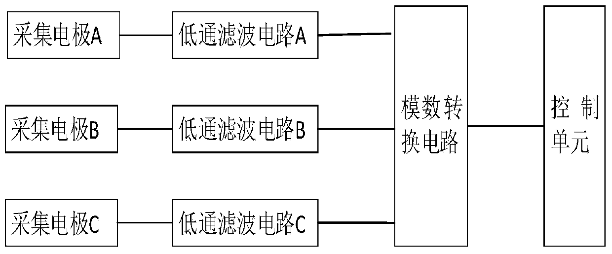
[0037] A kind of EEG signal acquisition device of the present invention, such as figure 1 As shown, it includes EEG signal acquisition electrodes, low-pass filter circuit, analog-to-digital conversion module, and control unit. After the signal is filtered by a low-pass filter circuit, it is input to the analog-to-digital conversion module to be converted into a brain digital signal, and then input to the control unit for calculation and processing.

[0038] In a specific embodiment of the present application, three collection electrodes are included, namely: a positive collection electrode for EEG signals, a negative collection electrode for EEG signals, and a reference collection electrode for EEG signals. Each collecting electrode is respectively connected with a low-pass filter circuit for performing low-pass filtering on the electroencephalogram signals collected by each collecting electrode.

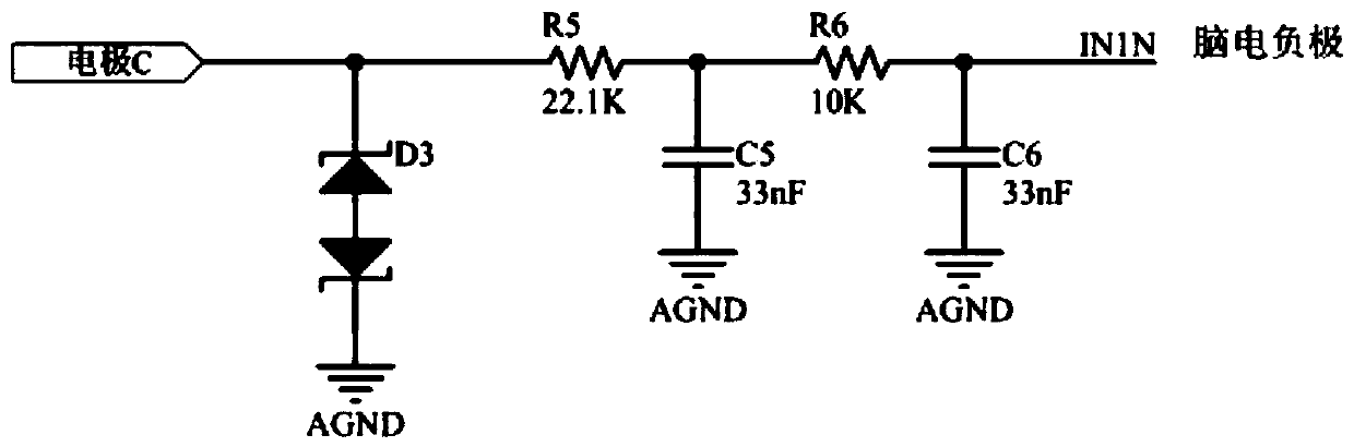
[0039] Specifically, the three low-pass filter circuits have the same structur...

specific Embodiment approach 2

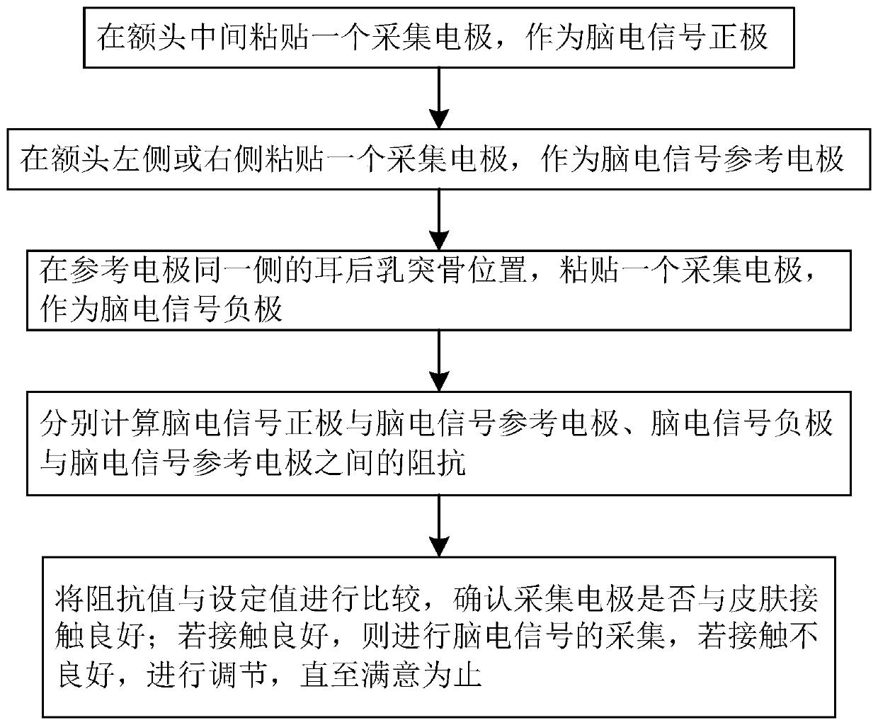
[0053] A method for collecting EEG signals, such as figure 2 shown, including the following steps:

[0054] S1. Paste an acquisition electrode in the middle of the forehead as the positive electrode of the EEG signal;

[0055] S2. Paste an acquisition electrode on the left or right side of the forehead as a reference electrode for EEG signals;

[0056] S3. Paste an acquisition electrode on the position of the mastoid bone behind the ear on the same side as the reference electrode, as the negative electrode of the EEG signal;

[0057] S4. Calculate the impedance between the positive electrode of the EEG signal and the reference electrode of the EEG signal, and the negative electrode of the EEG signal and the reference electrode of the EEG signal;

[0058] S5. Compare the impedance value with the set value to confirm whether the acquisition electrode is in good contact with the skin; if the contact is good, collect the EEG signal; if the contact is not good, adjust until it i...


PUM


Abstract

The invention discloses an electroencephalogram signal acquisition device and method. According to the method, the acquisition electrodes are adhered onto the middle of a forehead, the left side or the right side of the forehead and a mastoid bone behind an ear on the same side of the left or the right side of the forehead, the acquisition electrode of the left side and the forehead serves as a reference electrode, a constant alternating-current signal is inputted onto the skin through the reference electrode, impedance among the other two acquisition electrodes and the reference electrode iscalculated, the impedance is detected by a time sharing method, electroencephalogram signals are acquired by a time sharing method, contact states among the acquisition electrodes and the skin are monitored in real time, close contact among the acquisition electrodes and the skin is ensured, acquisition accuracy of the electroencephalogram signal is improved, interference signals are filtered outby the aid of a second-order low-pass filtering circuit, interference signals of the electroencephalogram signals are removed, and follow-up processing of the electroencephalogram signals is guaranteed.

Description

technical field [0001] The present invention relates to the technical field of electroencephalogram signals, in particular to a device and method for collecting electroencephalogram signals. Background technique [0002] Electroencephalogram signal (EEG) is a kind of potential activity generated by brain nerves, which contains rich information of brain activity, and is the main signal source in the study of anesthesia depth monitoring. However, since the electroencephalogram signal (EEG) is very weak, at the microvolt (uV) level, it is easily disturbed by the external environment. If the disturbed signal is not processed, it will greatly affect the measurement of parameters related to the depth of anesthesia. Among these interference sources, there are power supply noise, power frequency noise and electrode wire shaking and pulling interference introduced by the anesthesia depth monitoring equipment circuit, as well as the patient's own body movement, electrocardiogram (ECG)...

Claims


Application Information

Patent Timeline
Patent Type & Authority Applications(China)
IPC IPC(8): A61B5/0476A61B5/0478A61B5/00
CPCA61B5/7225A61B5/725A61B5/291A61B5/369
Inventor 杜武松
Owner 深圳市杰纳瑞医疗仪器股份有限公司
Why Eureka
Try Eureka