Buffer coupling

A coupling and pillow block technology, applied in the field of machinery, can solve the problems of coupling or related transmission parts damage, large impact torque, etc., and achieve the effects of reducing peak value, protecting safety, and prolonging transmission time.

Inactive Publication Date: 2020-03-06
HOHAI UNIV CHANGZHOU
View PDF5 Cites 0 Cited by
  • Summary
  • Abstract
  • Description
  • Claims
  • Application Information

AI Technical Summary

Problems solved by technology

The existing coupling rigidly connects the two, but when the driving shaft starts, due to the inertial load of the driven part connected to the driven shaft, the driving shaft will generate an impact load and form a large impact moment. When the driven part connected to the driving shaft is subjected to an impact load, the rigid connection between the driving shaft and the driven shaft will also form a large impact moment
It is easy to cause damage to the coupling or related transmission parts

Method used


Image

  • Buffer coupling

Examples


Embodiment Construction

[0013] The present invention will be further described below in conjunction with the accompanying drawings. The following examples are only used to illustrate the technical solution of the present invention more clearly, but not to limit the protection scope of the present invention.

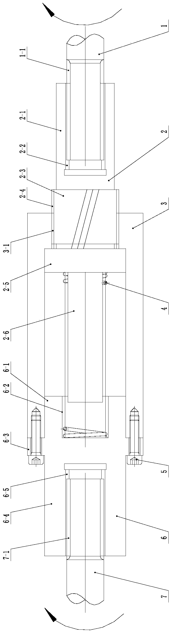
[0014] Such as figure 1 As shown, a buffer coupling includes a driving shaft 1, an intermediate shaft 2, an intermediate shaft sleeve 3, a cylindrical spring 4, a screw 5, a driven shaft spline sleeve 6 and a driven shaft 7;

[0015] The outer surface of the cylinder at the left end of the drive shaft 1 is processed with splines to form a drive shaft spline shaft 1-1; the intermediate shaft 2 includes the first pillow block 2-1 of the intermediate shaft and the second pillow block 2-3 of the intermediate shaft , the third pillow block 2-5 of the intermediate shaft and the cylindrical spring guide column 2-6; the inside of the first pillow block 2-1 of the intermediate shaft is processed with a ...


PUM


Abstract

The invention discloses a buffer coupling. The buffer coupling comprises a driving shaft, a middle shaft, a middle shaft sleeve, a cylindrical spring, screws, a driven shaft spline sleeve and a drivenshaft. The cylindrical spring is pre-compressed at the original position and used for balancing the limit transmission torque of a mechanism; and the cylindrical spring is further compressed when being subjected to impact torque to generate axial displacement and rotationally rotates corresponding to the circumferential direction, and a rotation speed difference is generated between the driven shaft and the driving shaft, so that the transmission time of the impact torque is prolonged, the peak value of the impact torque is reduced, and the safety of a transmission shaft and all parts in a transmission system is effectively protected.

Description

technical field [0001] The invention relates to a buffer coupling and belongs to the technical field of machinery. Background technique [0002] Couplings are mechanical general parts, which are mechanical parts used to connect the driving shaft and driven shaft in different mechanisms and make them rotate together to transmit torque. The existing coupling rigidly connects the two, but when the driving shaft starts, due to the inertial load of the driven part connected to the driven shaft, the driving shaft will generate an impact load and form a large impact moment. When the driven part connected to the driving shaft is subjected to an impact load, the rigid connection between the driving shaft and the driven shaft will also form a large impact moment. It is easy to cause damage to the coupling or related transmission parts. Contents of the invention [0003] In order to overcome the above-mentioned deficiencies, the present invention provides a buffer coupling, the tec...

Claims


Application Information

Patent Timeline
Patent Type & Authority Applications(China)
IPC IPC(8): F16D3/56F16D7/00
CPCF16D3/56F16D7/00
Inventor 钱雪松
Owner HOHAI UNIV CHANGZHOU
Why Eureka
Try Eureka