Buffer connection mechanism of transmission shaft

A connection mechanism and transmission shaft technology, applied in couplings, mechanical equipment, elastic couplings, etc., can solve the problems of low efficiency, large work loss, short life, etc., to extend the transmission time, protect safety, reduce peak value Effect

Active Publication Date: 2020-01-31
HOHAI UNIV CHANGZHOU
View PDF5 Cites 0 Cited by
  • Summary
  • Abstract
  • Description
  • Claims
  • Application Information

AI Technical Summary

Problems solved by technology

As a result, the coupling wears a lot and has a short life. At the same time, it cannot completely transmit

Method used


Image

  • Buffer connection mechanism of transmission shaft

Examples


Embodiment Construction

[0019] The present invention will be further described below in conjunction with the accompanying drawings. The following examples are only used to illustrate the technical solution of the present invention more clearly, but not to limit the protection scope of the present invention.

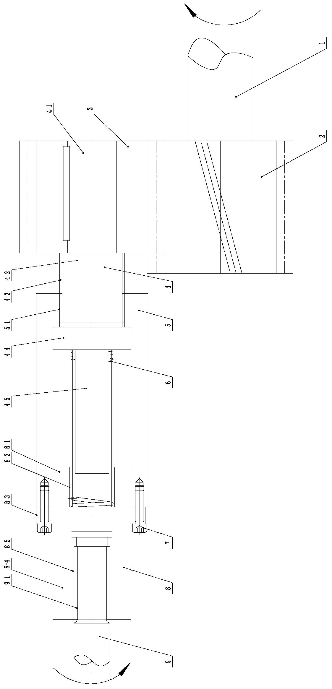
[0020] Such as figure 1 As shown, a buffer connection mechanism of a transmission shaft includes a driving shaft 1, a driving helical gear 2, a driven helical gear 3, an intermediate shaft 4, an intermediate shaft sleeve 5, a cylindrical spring 6, a screw 7, and a driven shaft spline sleeve 8 and driven shaft 9;

[0021] A tight fitting and reliable connection is formed between the driving shaft 1 and the driving helical gear 2, and the driving helical gear 2 meshes with the driven helical gear 3;

[0022] The intermediate shaft 4 includes the first pillow block 4-1 of the intermediate shaft, the second pillow block 4-2 of the intermediate shaft, the third pillow block 4-4 of the intermediate ...


PUM


Abstract

The invention discloses a buffer connection mechanism of a transmission shaft. The buffer connection mechanism comprises a driving shaft, a driving helical gear, a driven helical gear, an intermediateshaft, an intermediate shaft sleeve, a cylindrical spring, a screw, a driven shaft spline sleeve and a driven shaft. According to the buffer connection mechanism, the cylindrical spring is pre-compressed at the original position and is used for balancing the limit transmission moment of the mechanism; when the action of the impact moment is born, the cylindrical spring is further compressed to generate axial displacement corresponding to the circumferential rotation motion, so that the rotational speed difference is generated between the driven shaft and the driving shaft, the transmission time of the impact moment is prolonged, the peak value of the impact moment is reduced, and the safety of each component in the transmission shaft and the transmission system is effectively protected.

Description

technical field [0001] The invention relates to a buffer connection mechanism of a transmission shaft, which belongs to the technical field of machinery. Background technique [0002] Most of the existing transmission shaft buffer connection mechanisms are rigid couplings. When the driving shaft is started, due to the action of the inertial load of the driven shaft, an impact load is generated and a large impact moment is formed. When the driven shaft is subjected to the impact load , The rigid connection between the driving shaft and the driven shaft forms a large impact moment. As a result, the shaft coupling wears a lot and has a short life. At the same time, the power of the drive motor and the drive shaft of the protector cannot be completely transmitted, resulting in large work loss and low efficiency. Contents of the invention [0003] In order to overcome the above disadvantages, the present invention provides a buffer connection mechanism for transmission shafts,...

Claims


Application Information

Patent Timeline
IPC IPC(8): F16D3/06F16D7/00
CPCF16D3/06F16D7/00F16F15/12
Inventor 钱雪松
Owner HOHAI UNIV CHANGZHOU
Why Eureka
Try Eureka