Radiotherapeutic apparatus

a technology of radiotherapy and apparatus, applied in radiation therapy, radiation therapy, x-ray/gamma-ray/particle irradiation therapy, etc., can solve the problems of limiting the reducing the clinical quality of the plan, and not being able to deliver erdmlc in practice, so as to reduce the unwanted dose, reduce the dose rate of the arc, and more flexibility

Active Publication Date: 2013-08-06
ELEKTA AB
View PDF10 Cites 7 Cited by
  • Summary
  • Abstract
  • Description
  • Claims
  • Application Information

AI Technical Summary

Benefits of technology

[0022]If the optimisation in the Treatment planning computer was to be allowed to vary the mu per degree, then it would put more dose into gantry angles that have fewer critical organs in the path of the radiation. For example, when treating the prostate, as the gantry rotates the bladder and rectum come in and out of the path of the radiation. It is not possible to avoid irradiating these organs completely, nor is it desirable (otherwise insufficient dose could be deposited into the prostate) but if the optimisation is allowed more flexibility in controlling the dose to these critical organs then it will be able to reduce the unwanted dose.
[0023]If the dose rate for the arc can be lowered, this will allow the planning more flexibility but increase the time for delivery, which is undesirable. An aim of this invention is to remove such constraints from the treatment planning process and therefore maximise the quality of the plan, while at the same time retaining a quick delivery time. Quick delivery times are important for departmental efficiency and (in high precision Image Guided Radiation Therapy) to prevent organ motion between imaging and the completion of irradiation.
[0034]It is preferred that the beam axis and the axis of rotation of the source are substantially orthogonal, for reasons of geometric simplicity.

Problems solved by technology

However, it has not proved possible to deliver ERDMLC in practice.
This requires constraints to be placed on the treatment planning optimisation which degrade the clinical quality of the plan.
This is also a constraint in the planning, limiting the quality of the plan.
If the dose rate for the arc can be lowered, this will allow the planning more flexibility but increase the time for delivery, which is undesirable.

Method used


Image

  • Radiotherapeutic apparatus
  • Radiotherapeutic apparatus
  • Radiotherapeutic apparatus

Examples


Embodiment Construction

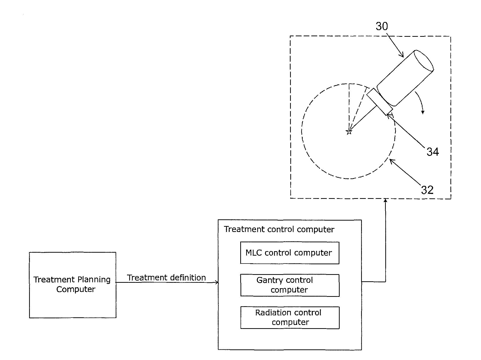
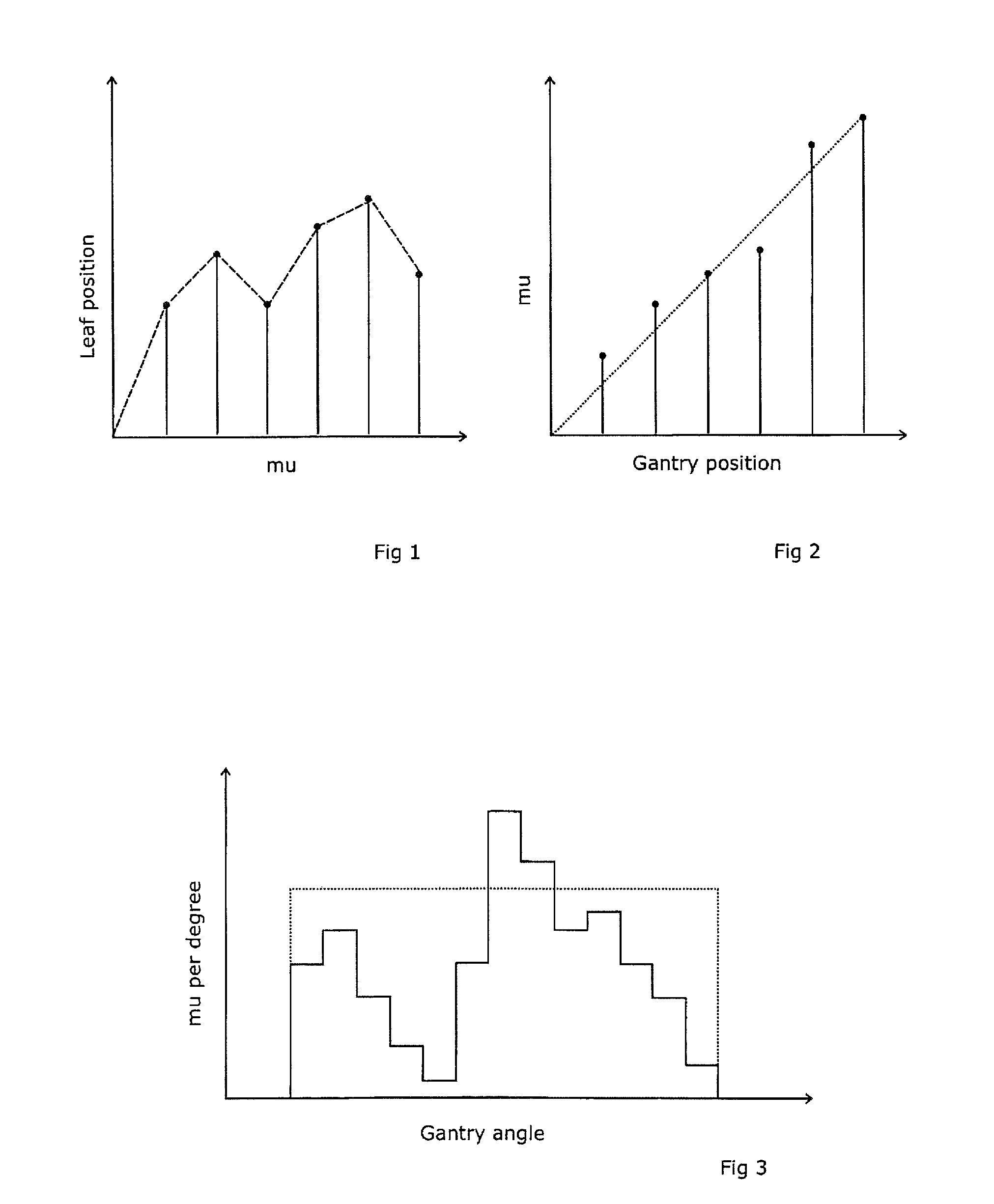
[0049]A desired treatment is described by a Treatment Planning computer in terms of a sequence of “control points”. Each “control point” defines a position of the gantry, the dose that is to be delivered between this and the next (or previous) control point, and the shape of the MLC at that control point. Each consecutive pair of control points defines (between them) an arc-segment.

[0050]Control points could (in theory) be spaced strategically around the complete arc. However, the availability of relatively cheap processing power means that there is little benefit in going to the effort of doing so, and control points are therefore typically spaced regularly around the arc such as every degree, every few degrees, or every fraction of a degree.

Basic Methodology

[0051]This treatment is put into effect by, between the nth and the (n+1)th control point, moving the gantry from the position of the nth control point to the position of the (n+1)th control point at a rotation speed and a dose...


PUM


Abstract

Apparatus comprising a radiation source which can rotate in an arc around the radiation beam axis, a multi-leaf collimator (MLC), and a controller for the source dose / time rate, the source rotation speed, and the MLC position. The controller calculates the time required for (i) an MLC leaf movement from start to end of an arc-segment at a maximum leaf speed, (ii) rotation of the source from start to end of the arc-segment at a maximum speed, and (iii) delivery of the dose at a maximum dose rate per time, selects the longest of (i), (ii) and (iii), and operates the selected one at its maximum and the others at a reduced rate matching that longest time, the time required for (i) and / or (ii) being the greater of the time to complete the segment at a continuous speed and the time to accelerate the item to that speed.

Description

[0001]This Application is a Section 371 National Stage Application of International Application No. PCT / EP2007 / 009227, filed Oct. 24, 2007 and published as WO 2009 / 052845 A1 on Apr. 30, 2009, the content of which is hereby incorporated by reference in its entirety.FIELD OF THE INVENTION[0002]The present invention relates to radiotherapeutic apparatus.BACKGROUND ART[0003]A radiotherapeutic apparatus is typically controlled by a Treatment Control Computer. When equipped with a Multi-Leaf Collimator (“MLC”) the Treatment Control Computer can be considered to contain a Radiation Control Computer which controls the radiation generation, an MLC Control computer which controls the shape of the MLC and a Gantry Control Computer which controls the position of the Gantry. These computers may physically be one or more computers but in this text are considered as distinct functional elements of the system. “Mu” is an abbreviation for “monitor units”, which is the term used for units of radiatio...

Claims


Application Information

Patent Timeline
Patent Type & Authority Patents(United States)
IPC IPC(8): A61N5/10
CPCA61N5/103A61N5/1042A61N5/1036
Inventor BROWN, KEVINSTREAMER, RALPHBOXALL, PAULBOURNE, DUNCANGIBSON, CHRISTOPHER JAMES
Owner ELEKTA AB
Why Eureka
Try Eureka