

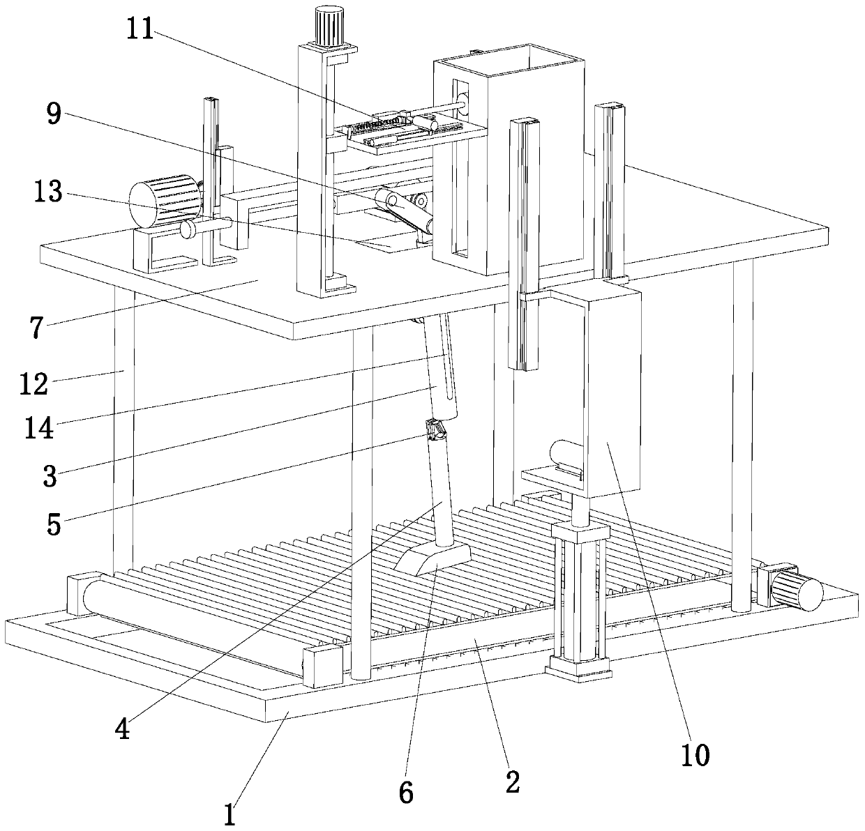
Prosthesis testing equipment
A technology for testing equipment and prostheses, which is applied in the field of prosthetics testing equipment, can solve the problems of not being able to truly feedback the performance of the knee joint, inconsistent state, ignoring the consistency of thigh and calf movement, etc., to achieve accurate walking performance, prevent slipping, and increase friction force effect
- Summary
- Abstract
- Description
- Claims
- Application Information
AI Technical Summary
Problems solved by technology
Method used
Image

Examples
Embodiment Construction
[0032] The technical solutions of the present invention will be clearly and completely described below in conjunction with the accompanying drawings. Apparently, the described embodiments are some of the embodiments of the present invention, but not all of them.
[0033] The components of the embodiments of the invention generally described and shown in the figures herein may be arranged and designed in a variety of different configurations. Accordingly, the following detailed description of the embodiments of the invention provided in the accompanying drawings is not intended to limit the scope of the claimed invention, but merely represents selected embodiments of the invention.
[0034] Based on the embodiments of the present invention, all other embodiments obtained by persons of ordinary skill in the art without making creative efforts belong to the protection scope of the present invention.
[0035] In the description of the present invention, it should be noted that the...
PUM
 Abstract
Description
Claims
Application Information