
A Rotating Logarithmic Periodic Antenna with Automatic Expansion and Retraction

A logarithmic periodic antenna, automatic technology, applied in the direction of rotating antenna, folding antenna, antenna support/installation device, etc., can solve the problem that the antenna cannot meet the user's needs for rapid deployment and retraction of the antenna, and is easy to grasp and implement. Technically feasible, small size effect

Active Publication Date: 2021-10-12
中国电波传播研究所
View PDF8 Cites 0 Cited by
  • Summary
  • Abstract
  • Description
  • Claims
  • Application Information

AI Technical Summary

Problems solved by technology

With the improvement of use requirements, the original antennas used in some projects can no longer meet the user's needs for rapid deployment and retraction of antennas

Method used


Image

  • A Rotating Logarithmic Periodic Antenna with Automatic Expansion and Retraction
  • A Rotating Logarithmic Periodic Antenna with Automatic Expansion and Retraction
  • A Rotating Logarithmic Periodic Antenna with Automatic Expansion and Retraction

Examples


Embodiment 1

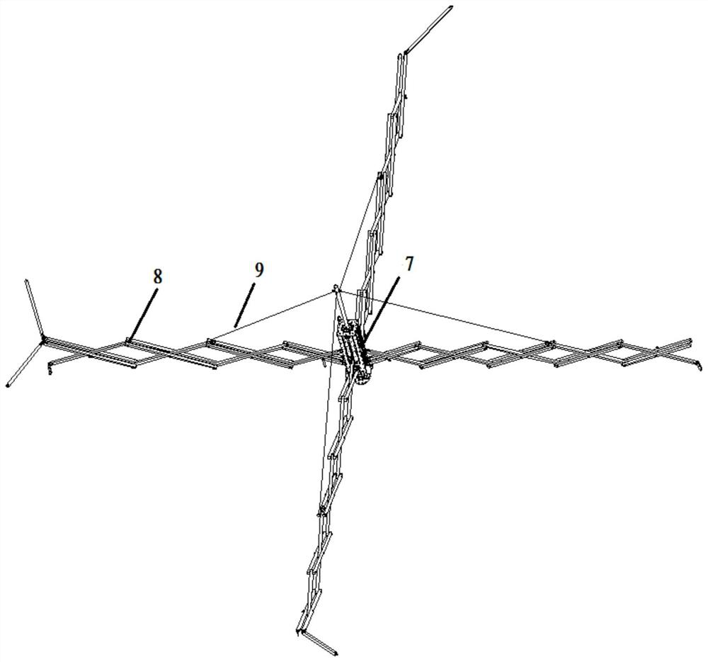
[0021] Example 1, such as figure 1 As shown, this embodiment discloses a rotating log-periodic antenna that automatically expands and retracts, including a bottom turntable system 3, and an antenna support 2 installed on the turntable system, such as figure 2 , shown in 3, the antenna support includes a retractable mechanism 7, a screw lifter, a guide rail and a slide block are built in the retractable mechanism, and the spiral lifter realizes the unfolding and folding of the antenna, and a pull rod 14 is installed on the top of the retractable mechanism, four The roots of the scissor-fork support truss 8 assembled from square tubes and pins are respectively installed on the four sides of the retractable mechanism, and the middle part is connected with the retractable mechanism through pins to realize the deployment and retraction of the antenna. The four support trusses The other ends of the four truss stay wires 9 installed on the stay rods are respectively connected to a s...


PUM


Abstract

The invention discloses an automatically retractable rotary logarithmic periodic antenna, which includes a bottom turntable system and an antenna support installed on the turntable system. The antenna support includes a retractable mechanism, and a spiral elevator and a guide rail are built in the retractable mechanism. and sliders, install the pull rod on the top of the retractable mechanism, and the roots of the four scissor-fork support trusses assembled by square tubes and pin shafts are respectively installed on the four sides of the retractable mechanism, and the middle part and the retractable mechanism pass through. Connected by pins, the four supporting trusses form a cross in pairs. The rotating logarithmic periodic antenna disclosed by the invention has the advantages of simple design method, feasible technology and convenient application. Compared with the original form of manually disassembled and assembled antenna, the antenna can be unfolded and folded quickly, with fewer operators, small size after folded, and easy storage and transportation.

Description

technical field [0001] The invention belongs to the field of communication antennas, in particular to an automatically unfolding and retracting rotating logarithmic periodic antenna in the field. Background technique [0002] With the increasing demand for mobile communications, the requirements for the ease of use of vehicle-mounted, ship-mounted, and airborne antenna structures are also getting higher and higher. At present, commonly used vehicle-mounted antennas are mainly installed and disassembled manually. Vehicle-mounted log-periodic antennas often use tube and rod structures as antenna supports, and wires as antenna surfaces. This type of antenna structure is time-consuming and laborious to disassemble. Furthermore, the installation and erection time requirements for mobile antennas are getting shorter and shorter. Users hope to quickly complete the antenna erection and use the antenna for communication in the shortest time. With the improvement of use requirements,...

Claims


Application Information

Patent Timeline
Patent Type & Authority Patents(China)
IPC IPC(8): H01Q1/08H01Q1/12
CPCH01Q1/084H01Q1/12
Inventor 宋宗凤刘毅王佐祥卢剑锋郭伟何绍林魏燊王鸿志李焕庆刘伟
Owner 中国电波传播研究所
Learn More