
Portable tool machine fixation frame

A technology of machine tools and fixing frames, which is applied in the field of movable machine tool fixing frames, can solve the problems of easy accidents, inability to install different sizes or other types of machine tools, and time-consuming problems

Inactive Publication Date: 2006-05-03
P & F BROTHER INDAL
View PDF0 Cites 0 Cited by
  • Summary
  • Abstract
  • Description
  • Claims
  • Application Information

AI Technical Summary

Problems solved by technology

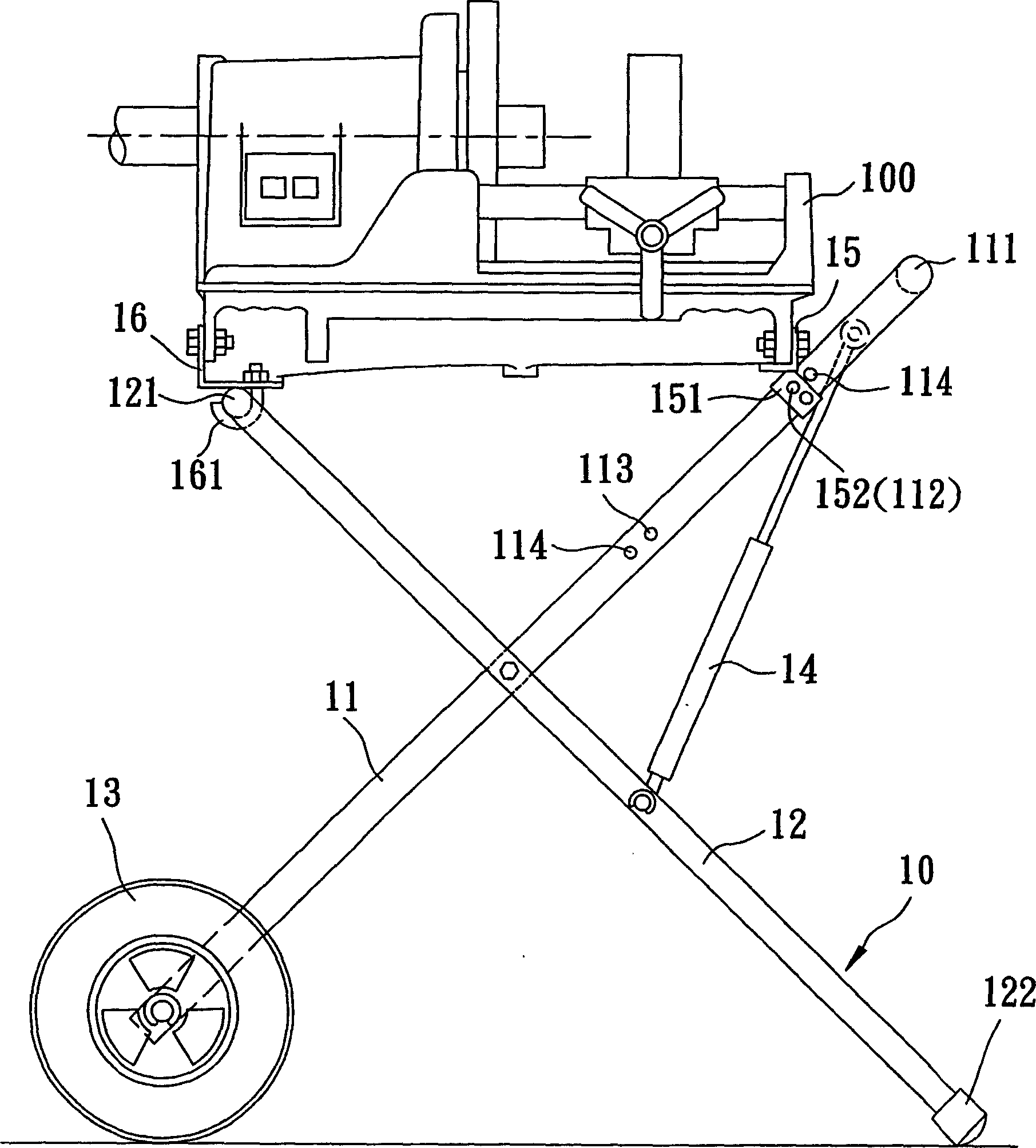
[0003] Although the above-mentioned fixed frame 10 has the functions of collapsible use and convenient movement, its usability still has its shortcomings and needs to be improved. In order to prevent the machine tool 100 from falling suddenly and cause danger, the user must first hold one end of the machine tool 100 with one hand, and insert or pull out the fixing pin 152 with the other hand. 1. The second support rods 11, 12 are pressed and folded, and the folding action is difficult and time-consuming. Moreover, because the fixed frame 10 is equipped with wheels 13, it is easy to roll and move freely without a point of force. Collapsing under the control of the focus point is often prone to accidental danger. In addition, the machine tool 100 is installed on the front and rear load bars 15, 16. The front load bar 15 is aligned with the first and second positioning holes 112. , 113, the relative distance between the front and rear bearing rods 15, 16 is fixed, so the traditional fixing frame 10 is only suitable for installing the machine tool 100 of the same specification, and cannot be used for installing machine tools of different sizes or other types. , the installation applicability is poor

Method used


Image

  • Portable tool machine fixation frame
  • Portable tool machine fixation frame
  • Portable tool machine fixation frame

Examples


Embodiment Construction

[0035] The foregoing and other technical contents, features and effects of the present invention will be clearly presented in the following detailed description of a preferred embodiment with reference to the drawings.

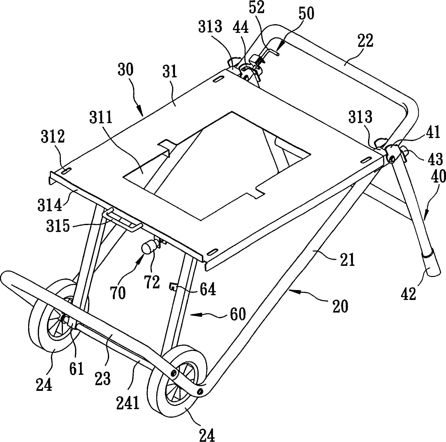
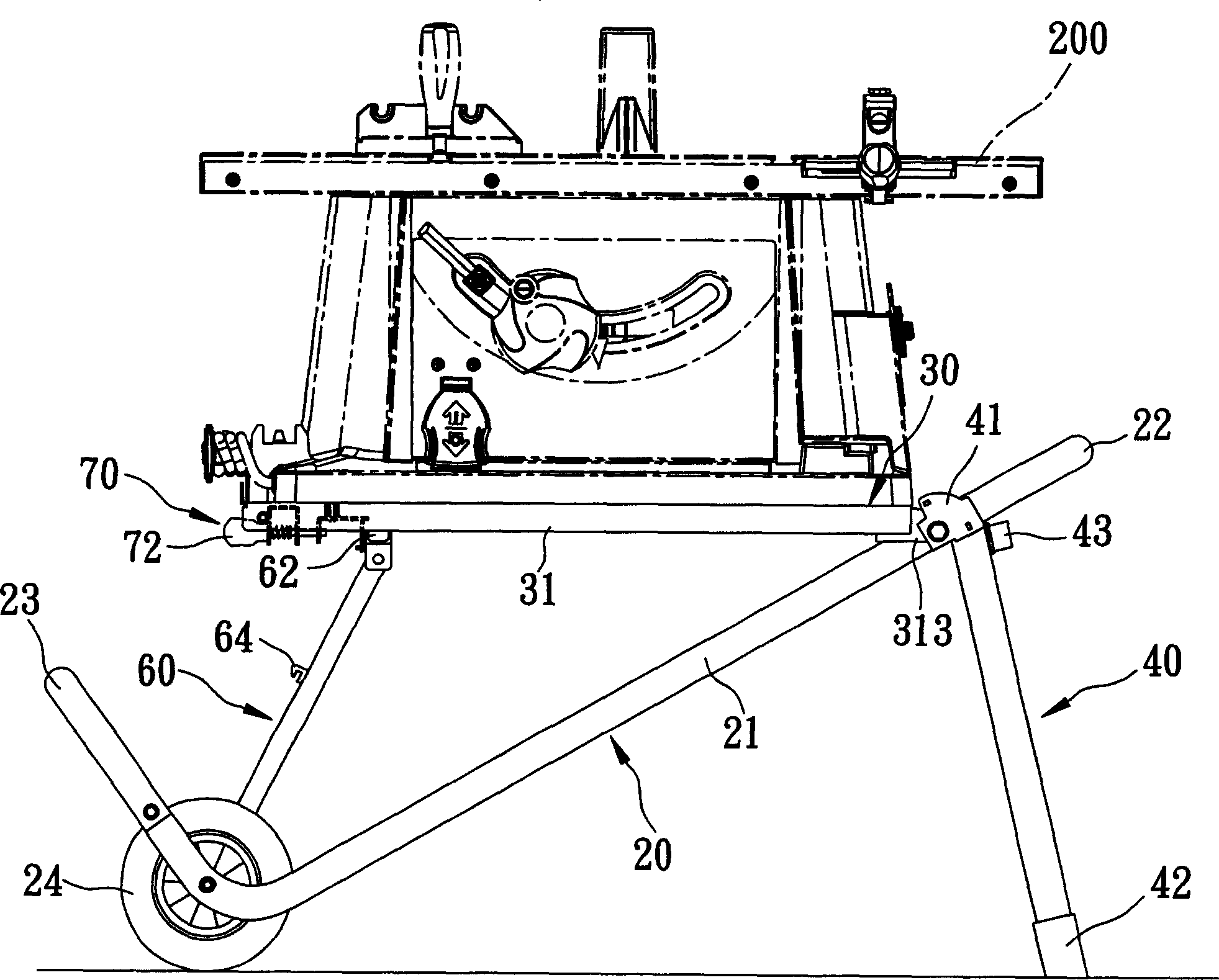
[0036] see figure 2 , image 3 As shown, in a preferred embodiment, the movable machine tool holder of the present invention includes a wheel carrier 20, a platform unit 30, a front foot frame 40, a front locking unit 50, a rear foot frame 60 and a The rear locking unit 70, then, the shape and combination of the above components will be described in detail later.

[0037] The wheel carrier 20 is a slightly L-shaped frame, which has a main frame rod 21, a handle rod 22 connected to the upper end of the main frame rod 21, and a 90-degree bent extension from the lower end of the main frame rod 21. The upright blocking bar 23 and the wheels 24 at the lower end of the main frame bar 21 are arranged on two axles, and a wheel axle 241 is horizontally arranged in t...


PUM


Abstract

Disclosed a movable fixing bracket of tool machine comprises: a wheel-carrier and a platform part, wherein, said wheel-carrier has a main hack lever and a handle rod; the platform part has a platform and a sliding rail base; the front side of platform has a pin joint end hinged with main hack lever, while its back has a free end; a front foot rest whose upper end has a ear part hinged with pin joint end while a protruded edge formed on the side of ear has first and second positioning hole; a front clamp unit which comprises a fixing base on the handle and a clamp rod flexibly mounted inside the fixing base; a back foot rest whose lower end has a axial fixing end hinged with wheel and upper end has a sliding end sliding mounted on the sliding rail base; the back foot rest has first and second clamp parts; and a back clamp unit comprising a fixing base fixed on the backside of platform, a drawing rod flexibly mounted in the fixing base and a clamp element linked with drawing rod. The invention can be transferred quickly and it can apply the installation of variable machines with easy operation.

Description

【Technical field】 [0001] The invention relates to a machine tool fixing frame, in particular to a movable tool machine fixing frame. 【Background technique】 [0002] see figure 1 As shown, there is a traditional machine tool fixing frame 10 comprising a first support rod 11, a second support rod 12, a pair of wheels 13, a group of hydraulic cylinders 14, a front load rod 15 and a rear load rod 16, The first and second support rods 11 and 12 intersect in the middle to be in the shape of a pivot, so that the first and second support rods 11 and 12 can be expanded or folded. The handle 111 held, the lower end can be used for the wheel 13 to be pivotally connected, and its shaft has a first positioning hole 112 and a second positioning hole 113 respectively at predetermined positions, adjacent to each positioning hole 112, 113 side places are provided There is a stop pin 114, the upper end of the second support rod 12 has a circular diameter cross bar 121, and the lower end has...

Claims


Application Information

Patent Timeline
Patent Type & Authority Applications(China)
IPC IPC(8): B25H5/00
Inventor 陈裕田蔡庆耀洪雅玲
Owner P & F BROTHER INDAL
Learn More