A Supermode Optical Fiber for Transmission of Orbital Angular Momentum

A technology for transmitting orbit and angular momentum, which is applied in the field of optical fiber communication, can solve the problems of reducing the mode area, small difference in refractive index between the ring core and the outer cladding, and easy deformation, so as to achieve high mode coupling intensity, enhanced light energy leakage, and limited The effect of low loss

Active Publication Date: 2021-06-29
四川天府江东科技有限公司
View PDF9 Cites 0 Cited by
  • Summary
  • Abstract
  • Description
  • Claims
  • Application Information

AI Technical Summary

Problems solved by technology

[0013] However, this scheme has the following disadvantages: (1) Each mode coupling unit of this scheme supports dual-mode transmission, that is, supports HE 1,1 with HE 2,1 mode, but HE 2,1 The coupling of modes is divided into two types, namely tangential coupling and normal coupling
Using this method to construct the outer cladding, when the air filling rate of the outer cladding is high, the proportion of the base material is small, the leakage channel is small, and the refractive index difference between the ring core and the outer cladding is large, so that the optical fiber has a strong ability to bind the optical field and low loss, but It will reduce the mode area; when the air filling rate of the outer cladding is low, the proportion of the substrate material is high, the leakage channel is wide, and the refractive index difference between the ring core and the outer cladding is small. Weak, high loss. For example, in the optical fiber designed by W.Wang et al., the maximum mode area at 1.55μm is 638.88μm while the loss meets the transmission requirements 2 , even the largest mode area at all working wavelengths is only 664.60μm 2 , which is significantly smaller than the area of ​​the ring core region (approximately 1100 μm 2 ); (4) There are still many air holes in the microstructure cladding, which are difficult to prepare, easy to deform during the drawing process, and the uniformity is not easy to control. At the same time, the long-term stability of the porous structure is weak
Therefore, the above series of shortcomings and contradictions determine that even if the number of orbital angular momentum modes supported by this scheme is large, it is difficult for the optical fiber to be stably transmitted and practically applied.

Method used


Image

  • A Supermode Optical Fiber for Transmission of Orbital Angular Momentum
  • A Supermode Optical Fiber for Transmission of Orbital Angular Momentum
  • A Supermode Optical Fiber for Transmission of Orbital Angular Momentum

Examples


Embodiment Construction

[0032] In order to more clearly illustrate the technical solutions in the embodiments of the present invention or the prior art, the following will briefly introduce the drawings that need to be used in the description of the embodiments or the prior art. Obviously, the accompanying drawings in the following description These are some embodiments of the present invention. Those skilled in the art can also obtain other drawings based on these drawings without creative work.

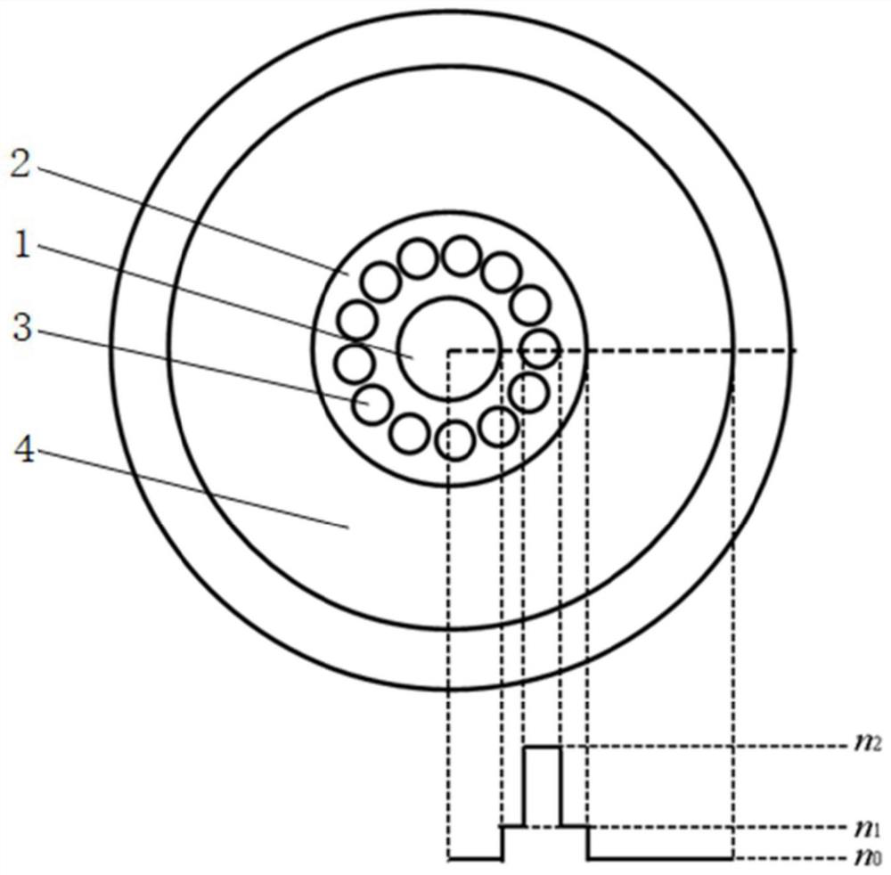
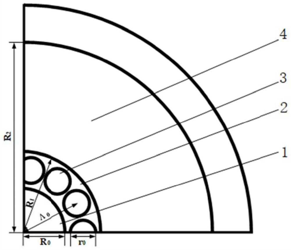
[0033] see figure 1 with figure 2 , a supermode optical fiber for transmitting orbital angular momentum proposed by the present invention, including a central solid cylinder 1 and an inner solid ring 2 arranged in sequence from the center to the outside, and the axial equiangular distribution on the inner solid ring 2 The high refractive index column 3 and the outer solid ring 4, the central solid cylinder 1 constitutes the inner cladding area of ​​the optical fiber, the inner solid ring 2 and the high r...


PUM


Abstract

A supermode optical fiber for transmitting orbital angular momentum, including a central solid cylinder, an inner solid ring, high refractive index columns distributed on the solid ring and an outer solid ring, an inner solid ring and a high refractive index column The ring core region, the central solid cylinder constitutes the inner cladding region, and the outer solid ring constitutes the outer cladding. Each mode coupling unit is single-mode transmission when the wavelength is greater than 1.2 μm. At the same time, the material of the central solid cylinder and the outer solid ring is the same and the refractive index is lower than that of the inner solid ring. The outer boundary of the central solid cylinder is the same as the inner solid ring. The inner boundary, the inner boundary of the outer solid ring and the outer boundary of the inner solid ring form a closed boundary with a refractive index gradient. The number of practically applicable modes of the present invention is equal to the number of theoretical modes, the ratio of the mode area to the area of ​​the ring core is high, and the solid structure is adopted, the design and drawing are simple, and it can be applied to long-distance high-power orbital angular momentum transmission, and can industrialization.

Description

technical field [0001] The invention relates to the field of optical fiber communication, in particular to a supermode optical fiber for transmitting orbital angular momentum. Background technique [0002] Most of the existing optical fiber communication networks use multiplexing technologies such as wavelength division multiplexing and time division multiplexing to expand capacity. With the rapid development of mobile communication services, Internet technologies such as cloud computing, Internet of Things, and big data are rising day by day, and the demand for communication capacity in the current highly informationized society is increasing day by day. Current technology is getting closer and closer to the Shannon limit. In order to expand the communication capacity, people have applied space division multiplexing technology to optical fiber communication in recent years. As another degree of freedom of light besides wavelength, intensity, frequency and polarization, or...

Claims


Application Information

Patent Timeline
Patent Type & Authority Patents(China)
IPC IPC(8): G02B6/02G02B6/036
CPCG02B6/02333G02B6/02342G02B6/03611
Inventor 王伟徐海东杨慢杨骐豪贾静静
Owner 四川天府江东科技有限公司
Why Eureka
Try Eureka